Understanding electrical schematics for high-voltage industrial equipment is a fundamental skill that significantly enhances practical electrical proficiency and ensures paramount safety. These visual guides are indispensable for anyone working with powerful machinery, serving as the definitive map of the electrical system. Mastering the interpretation of these intricate drawings not only demystifies complex circuits but also builds a strong foundation for a career in electrical maintenance, installation, or design, while minimizing risks associated with electrical work.
Proficiency in deciphering these electrical plans offers substantial advantages. It enables precise troubleshooting, allowing for swift identification and resolution of electrical faults, thereby reducing downtime and maintenance costs. Furthermore, it facilitates safer and more efficient installations, ensuring all components are connected correctly according to manufacturer specifications and electrical codes. With a comprehensive understanding, planning modifications or upgrades to existing systems becomes a confident and methodical process, preventing costly errors and ensuring optimal performance.
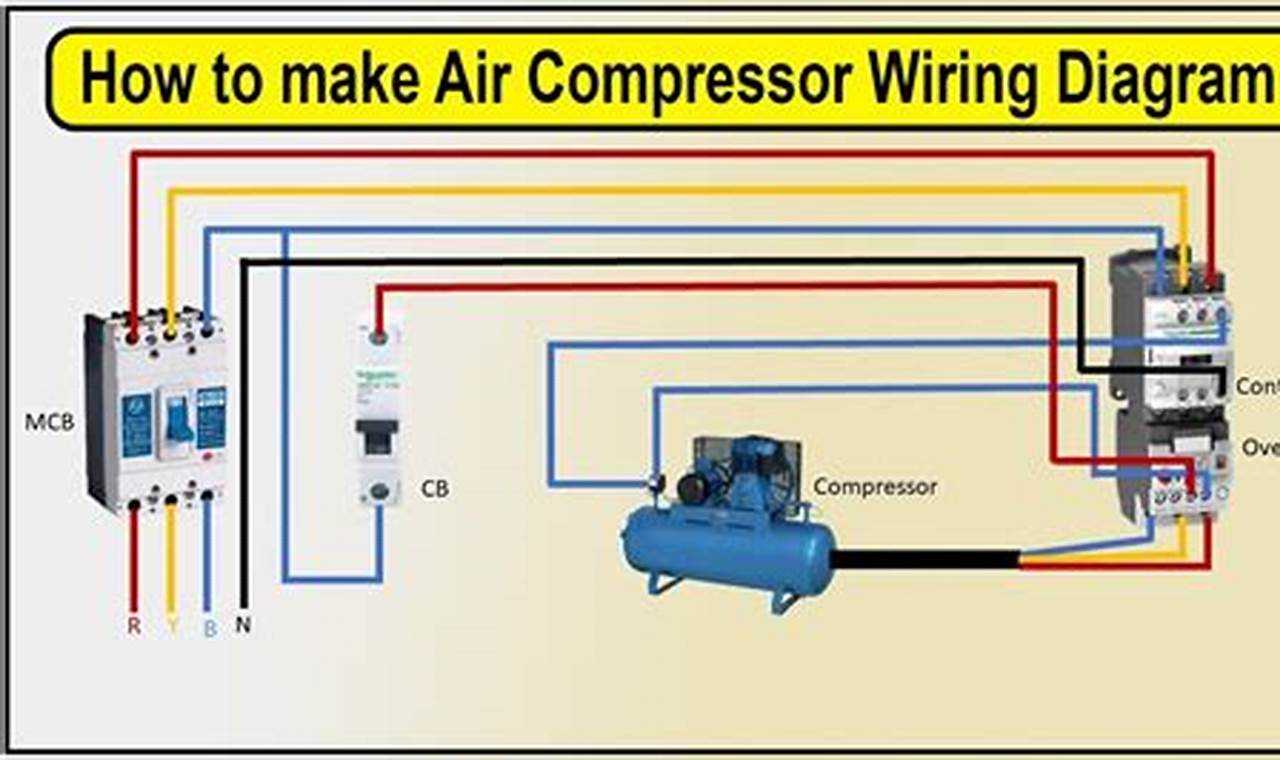
A typical electrical schematic for a high-voltage air compressor outlines various key elements, starting with the main power supply and branching out to the motor, pressure switch, magnetic contactor, thermal overload protector, and control circuitry. Standard electrical symbols are used universally to represent components such as circuit breakers, fuses, wiring connections, coils, normally open (NO) and normally closed (NC) contacts, and various indicators. Wires are often color-coded or numbered, and pathways are clearly delineated, illustrating both the power circuit (carrying the main current) and the control circuit (governing the operation of relays and contactors).
To effectively interpret and apply these electrical blueprints, a systematic approach is recommended. Begin by identifying the incoming power source and tracing the main power circuit through the disconnect switch, circuit protection device (e.g., fuses or circuit breakers), and the motor starter (contactor and overload relay) to the motor itself. Next, shift focus to the control circuit, which typically originates from a lower voltage tap and includes the pressure switch, start/stop buttons, and contactor coil. Pay close attention to the sequence of operations triggered by switches and relays. Practical application involves verifying component ratings against the diagram, ensuring correct wire sizing, and confirming all safety interlocks are properly connected, such as the thermal overload protecting the motor from excessive current.
For enhanced comprehension and practical safety, always de-energize circuits before attempting any work and verify with a multimeter. Familiarity with local electrical codes relevant to industrial equipment is crucial for compliant installations. Supplementing knowledge of a specific compressor’s electrical plan with broader understanding of motor control circuits, safety interlocks, and three-phase power systems will prove beneficial. Exploring diverse schematics for other industrial machinery, consulting manufacturer technical manuals, and utilizing online resources dedicated to electrical engineering principles can significantly deepen one’s expertise.
Mastering the art of interpreting electrical documentation for powerful machinery is an invaluable skill for anyone involved in electrical work. It is a cornerstone of safe, efficient, and reliable operation of complex systems. Continued engagement with various electrical diagrams and exploration of additional resources will solidify this foundational knowledge, empowering individuals to tackle increasingly sophisticated electrical challenges with confidence and precision. For further exploration of electrical resources and diagrams, readwires.com offers a wealth of information.
