Introduction
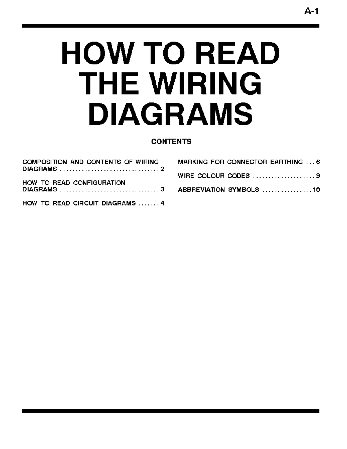
Reading wiring diagrams pdf files requires systematic visual decoding of standardized line weights, alphanumeric grid coordinates, and localized component callouts to trace electrical pathways accurately. According to SAE International, adhering to standardized automotive and industrial wire identification conventions prevents hazardous cross-wiring and significantly reduces diagnostic downtime in complex electrical architectures. Mastering this technical documentation format allows technicians and DIYers to navigate multi-page digital schematics effortlessly, cross-reference pinout locations, and isolate faulty grounds or open circuits within 12V automotive systems and residential Home Electrical Wiring Diagrams without guesswork.
Wiring Technical Snapshot:
- Core Focus: Systematic decoding of digital schematic files for electrical fault isolation.
- Target Scope: Automotive 12V/24V circuits, home electrical networks, and electronic devices.
- Key Recommendation: Utilize digital search tools and layer toggles in PDF readers to isolate single circuits.
Core Principles and Detailed Overview
Reading wiring diagrams pdf documents begins with mastering standardized schematic symbols, grid coordinate locators, and wire color-coding legends embedded within digital pages. Digital schematic files often utilize vector graphics, allowing users to zoom indefinitely without losing line clarity while utilizing search functions to locate specific pin numbers or component tags instantly. Technicians must differentiate between block diagrams that show system relationships and complete schematic diagrams that illustrate every individual wire, splice, and connector pin. Proper navigation of these documents relies on understanding power distribution paths, where voltage sources originate at the top or left of the page and flow downward or rightward toward system grounds, mirroring standard current flow conventions found in Wiring Diagram Basics.
Key Specifications and Breakdown
| Circuit / Terminal | Standard Wire Color / Gauge | Operational Role & Safety Check |
|---|---|---|
| Chassis Ground | Black / 12 AWG | Provides a low-resistance return path to the battery negative terminal; verify continuity with a digital multimeter. |
| Fused B+ Power | Red / 14 AWG | Delivers constant battery voltage to load centers; verify fuse integrity and voltage drop under operating load. |
| Switched Ignition | Yellow / 16 AWG | Activates accessory relays and control modules upon key turn; verify switch voltage output during cranking. |
Strict adherence to National Electrical Code (NEC) and NFPA 70 standards ensures that all circuit modifications, wire sizing selections, and protective device installations maintain verified thermal and mechanical safety thresholds. — National Fire Protection Association (NFPA)
Step-by-Step Practical Application and Guidelines
Reading wiring diagrams pdf manuals effectively requires a methodical diagnostic workflow that transitions from macro system overviews down to individual terminal pins. The process starts by locating the specific system page using the PDF table of contents or index bookmarks. Next, locate the power source at the top of the schematic and follow the line through switches, relays, and fuses until reaching the targeted load component. When servicing vehicle networks, cross-referencing connector face views—often detailed in supplementary Vehicle Wiring Diagrams—ensures probes are inserted into the correct cavity during live voltage testing. Finally, utilize digital annotation tools within the PDF viewer to highlight active test paths, mark verified continuity checks, and document voltage drops directly onto the document for future reference during Wiring Troubleshooting sessions.
Common Challenges and How to Avoid Them
Reading wiring diagrams pdf files frequently presents obstacles such as misinterpreting dashed versus solid lines, overlooking hidden inline splices, and getting lost across multi-page continuation markers. Technicians frequently fail to notice that a wire jumps from one page to another via alphanumeric grid coordinates like C4 or E2, leading to incorrect diagnostic assumptions. Another common error involves ignoring manufacturer-specific abbreviations for wire colors and connector genders, which can result in severe misdiagnoses. Avoid these pitfalls by thoroughly reviewing the schematic legend on the opening pages of the PDF document, utilizing software search tools to track wire code numbers across all indexed pages, and verifying physical component locations against actual hardware before performing intrusive electrical testing or component replacement.
💬 Frequently Asked Questions
Explore More Wiring Diagrams and Schematics on ReadWires
Mastering digital schematic interpretation empowers technicians, electricians, and DIY hobbyists to diagnose complex electrical faults safely and efficiently across domestic, automotive, and industrial applications. Access comprehensive technical resources, detailed pinout guides, and extensive reference archives by visiting the main library at ReadWires.com to support every upcoming electrical installation and diagnostic project.
Wiring Diagram Schematics & Details