Introduction
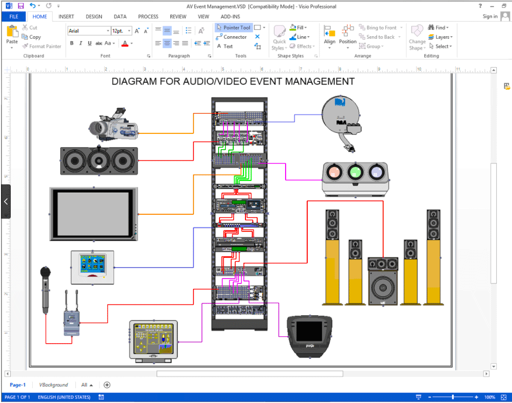
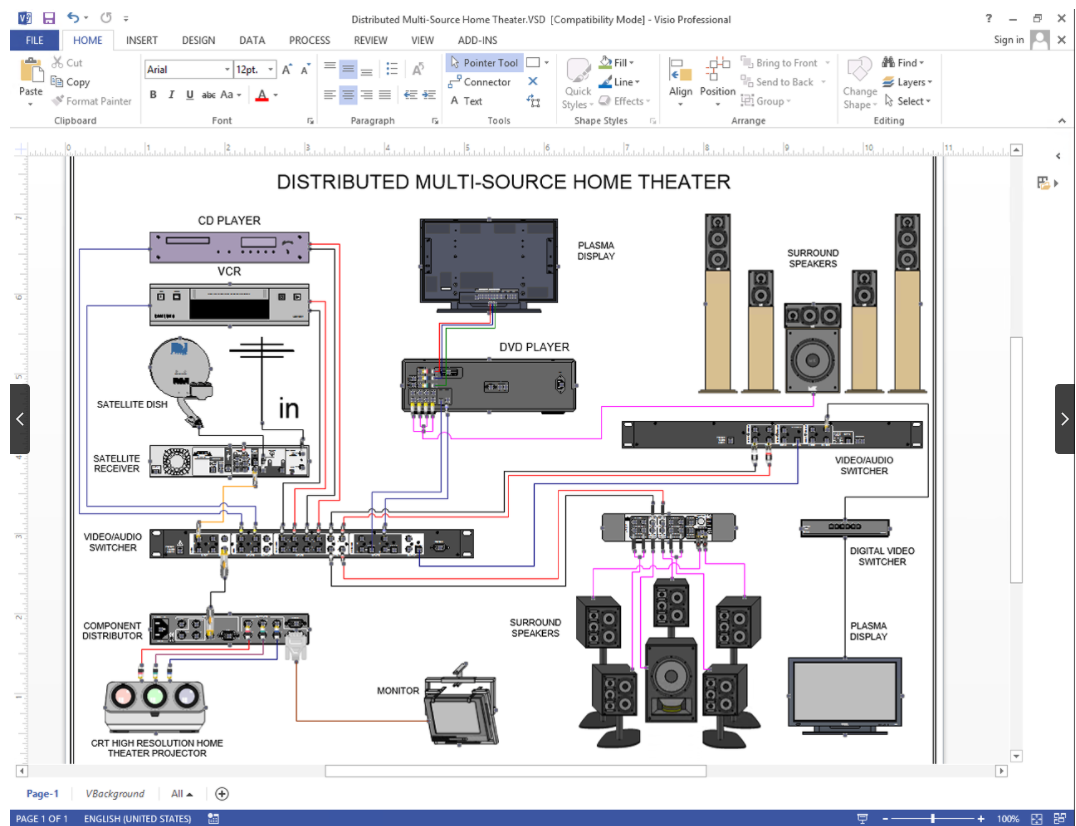
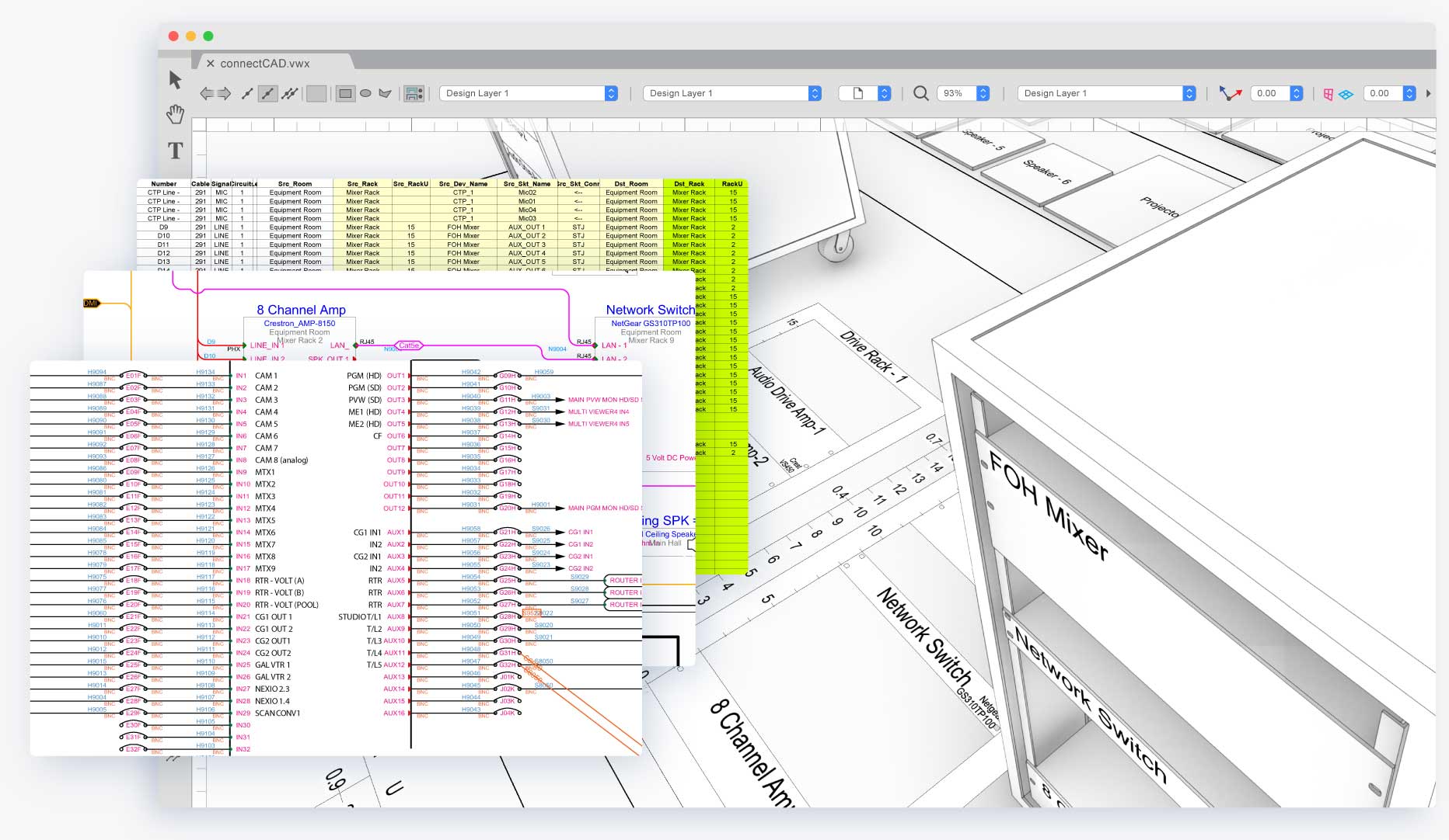
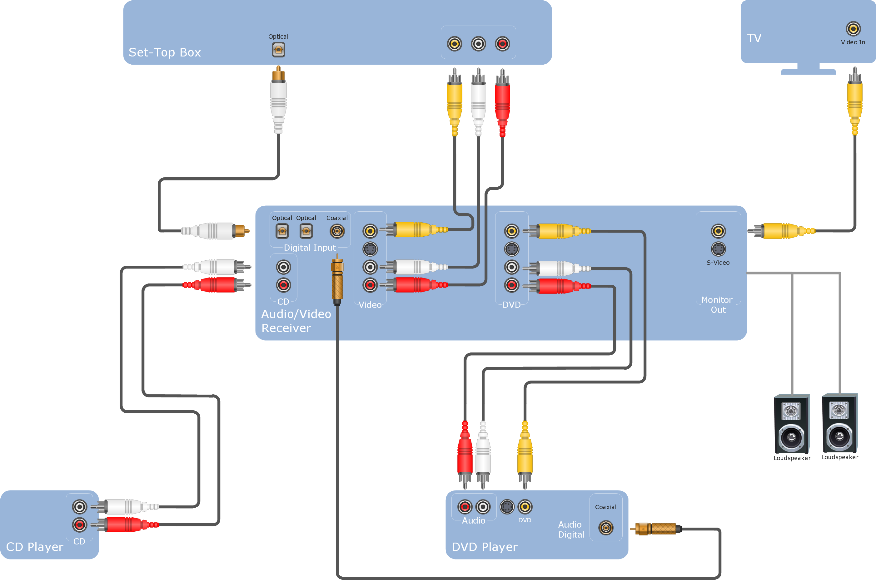
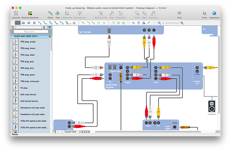
Audio wiring diagram software is specialized computer-aided design applications engineered to draft, simulate, and analyze electrical schematics for complex 12V automotive stereo networks and multi-zone architectural sound systems. According to SAE International, adherence to standardized electrical documentation ensures circuit reliability, prevents catastrophic short circuits, and maintains proper impedance matching across inductive loads. Technicians, automotive enthusiasts, and journeyman electricians rely on these digital routing tools to interpret factory harnesses, design custom amplifier integration layouts, and eliminate signal interference before physical hardware installation begins. Accurate schematics reduce diagnostic downtime, safeguard delicate audio processors from ground loops, and guarantee compliance with rigorous industrial power distribution frameworks. Readers seeking advanced layout strategies can reference specialized resources found within Audio and Entertainment Wiring Diagrams for deeper system integration insights.
Wiring Technical Snapshot:
- Core Focus: Digital design and simulation tools for 12V automotive and multi-channel home audio distribution networks.
- Target Scope: Applied in mobile electronics, custom vehicle dash integration, home theater setups, and systematic electrical troubleshooting.
- Key Recommendation: Validate all calculated load impedances against amplifier manufacturer specifications prior to finalizing physical wire runs.
Core Principles and Detailed Overview
Audio wiring diagram software transforms abstract electrical principles into clear, editable graphical schematics by mapping out power rails, remote turn-on triggers, low-level RCA paths, and high-level speaker channels. Modern software packages allow users to simulate voltage drops, calculate appropriate American Wire Gauge (AWG) dimensions based on current draw and run length, and verify fuse ratings to prevent thermal overload. In complex automotive upgrades, modern head units, digital signal processors (DSPs), and multi-channel amplifiers require precise pinout mapping to interface cleanly with factory CAN bus integration adapters. Utilizing structured digital schematics mitigates human error during multi-zone speaker configuration, ensuring proper positive and negative phase alignment which prevents acoustic cancellation and poor bass response. Professionals frequently cross-reference these digital workflows with foundational principles outlined in Wiring Diagram Basics to maintain standard symbol recognition across diverse platforms.
Key Specifications and Breakdown
| Circuit / Terminal | Standard Wire Color / Gauge | Operational Role & Safety Check |
|---|---|---|
| Constant 12V Battery Power | Yellow (10 AWG – 4 AWG) | Delivers unswitched high current to amplifiers; verify continuity and inline fuse proximity with a digital multimeter. |
| Remote Turn-On Lead | Blue / White Stripe (18 AWG) | Sends a low-current 12V trigger signal from head unit to activate relays and amplifiers; check for voltage drop under load. |
| Right Front Speaker Positive | Gray or Gray/Black Stripe (16 AWG) | Carries amplified audio signals to speaker voice coil; test impedance and phase polarity to prevent acoustic cancellation. |
Electrical conductors in mobile audio systems must maintain adequate cross-sectional area to prevent excessive voltage drop and thermal degradation under maximum continuous output. — National Fire Protection Association (NFPA)
Step-by-Step Practical Application and Guidelines
Executing a successful audio installation begins by importing factory vehicle schematics or architectural blueprints into the diagramming software to establish accurate node locations. The next phase involves drafting power distribution paths, isolating high-voltage power cables from sensitive low-level RCA signal wires to prevent electromagnetic induction and alternator whine. Users must accurately assign wire gauges, connector pins, and relay triggers within the software interface, generating a comprehensive blueprint that dictates physical wire stripping, crimping, and soldering procedures. Before connecting the vehicle battery or primary AC mains, technicians should utilize the software’s built-in simulation or validation checker to confirm that all ground points are properly bonded to bare chassis metal with zero measurable resistance. For advanced troubleshooting methodologies when encountering erratic signal behavior, consult the diagnostic guides available in Wiring Troubleshooting.
Common Challenges and How to Avoid Them
Wiring layout errors typically manifest as persistent ground loops, blown fuses, speaker distortion, or complete system silence due to incorrect impedance loads or poor chassis grounding. Software design helps prevent these pitfalls by enforcing strict rule checks for circuit capacity, but installers must still verify physical realities such as physical wire routing proximity and terminal crimp integrity. Ground loops occur when audio components reference different chassis potentials; digital schematic planning ensures all signal processors and amplifiers share a centralized, low-resistance grounding bus. Furthermore, failing to account for total speaker impedance dropping below amplifier stability thresholds can trigger thermal protection modes or damage output transistors. Systematic verification of every node on the digital schematic against the physical hardware installation remains the definitive method for achieving clean, reliable audio performance.
💬 Frequently Asked Questions
Explore More Wiring Diagrams and Schematics on ReadWires
Mastering electrical layouts requires continuous reference to verified schematics across diverse residential, automotive, and industrial applications. Expanding technical expertise involves exploring comprehensive documentation libraries, including specialized resources for Relay and Component Wiring Diagrams, to ensure safe, professional-grade installations on every project. Visit ReadWires.com to access a complete collection of authoritative wiring guides, schematics, and diagnostic insights.
Wiring Diagram Schematics & Details