Introduction
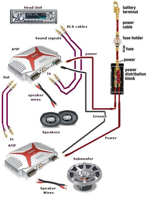
A wiring diagram car audio blueprint serves as the definitive schematic map outlining voltage pathways, ground returns, and speaker channel routing throughout an automotive 12V DC mobile electronics infrastructure. According to SAE International, adhering to standardized automotive wire color codes and gauge specifications defined in SAE J1128 ensures mechanical durability and prevents dangerous thermal overloads in mobile audio circuits. Reviewing proper schematics allows technicians to seamlessly integrate aftermarket head units, multi-channel amplifiers, and digital signal processors without compromising factory harnesses. Mastery of these schematics bridges the gap between basic electrical theory and flawless mobile entertainment installations, supporting deeper exploration into Vehicle Wiring Diagrams.
Wiring Technical Snapshot:
- Core Focus: Complete cartography of 12V constant power, switched ignition, chassis grounds, and low-level RCA or high-level speaker outputs.
- Target Scope: 12V/24V automotive electrical systems, custom mobile audio retrofits, and systematic diagnostic troubleshooting.
- Key Recommendation: Always disconnect the negative battery terminal before cutting or splicing any wire identified on the schematic.
Core Principles and Detailed Overview
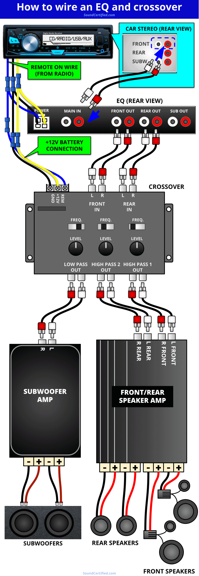
Reading a wiring diagram car audio schematic requires translating standardized alpha-numeric symbols, wire gauge numbers, and color abbreviation codes into physical circuit connections. The primary power input relies on a heavy-gauge 12V constant line feeding the head unit memory and amplifier reserve capacitors, paired with an accessory switched wire that triggers system activation upon key rotation. Technicians must differentiate between low-level line-out signals and high-level amplified outputs to avoid catastrophic impedance mismatches that destroy sensitive solid-state amplifier stages. Reference resources like Audio and Entertainment Wiring Diagrams provide critical layout configurations for complex multi-zone speaker architectures.
Key Specifications and Breakdown
| Circuit / Terminal | Standard Wire Color / Gauge | Operational Role & Safety Check |
|---|---|---|
| Constant 12V Power | Yellow / 10-14 AWG | Main battery feed; verified with a digital multimeter for continuous 12V potential. |
| Ignition / Accessory | Red / 16-18 AWG | Switched ignition signal; confirms head unit powers on only with key turned. |
| Chassis Ground | Black / 10-14 AWG | Direct return to bare metal chassis; verified for resistance under 0.5 ohms. |
Electrical conductors in mobile audio systems must be sized adequately for maximum continuous current draw to prevent excessive voltage drop and fire hazards — National Fire Protection Association (NFPA)
Step-by-Step Practical Application and Guidelines
Executing an audio installation safely involves matching factory wire harness designations to aftermarket wiring adapter color standards using a digital multimeter for continuity verification. Begin by cross-referencing the factory service manual with the aftermarket head unit schematic to identify critical lines including remote turn-on leads, illumination dimmers, and individual speaker phases. Strip insulation meticulously, apply mechanical crimps protected by dual-wall adhesive heat shrink tubing, and route power cables away from high-current ignition components to eliminate alternator whine or electromagnetic interference. Practicing methodical validation techniques directly aligns with insights found within Wiring Troubleshooting procedures.
Common Challenges and How to Avoid Them
Misinterpreting factory wire polarity or utilizing undersized power conductors frequently results in blown fuses, distorted audio output, and persistent ground loop hums. Technicians should never rely solely on wire color consistency across different vehicle manufacturers; always use a multimeter to verify DC voltage potentials and speaker impedance values prior to final component connection. Furthermore, establishing a solid, unpainted chassis ground point prevents high-resistance voltage drops that starve high-power amplifiers of required current during heavy bass transients. Proper planning through Wiring Diagram Basics helps eliminate these common installation pitfalls.
💬 Frequently Asked Questions
Explore More Wiring Diagrams and Schematics on ReadWires
Mastering automotive audio electrical integration requires access to accurate, comprehensive documentation across diverse systems and modern vehicle architectures. Continual professional development and diligent schematic review safeguard electronic components against miswiring and unexpected failure modes. Expand technical proficiency by browsing additional schematics, guides, and reference documents available directly through the primary repository at ReadWires.com.
Wiring Diagram Schematics & Details