Introduction
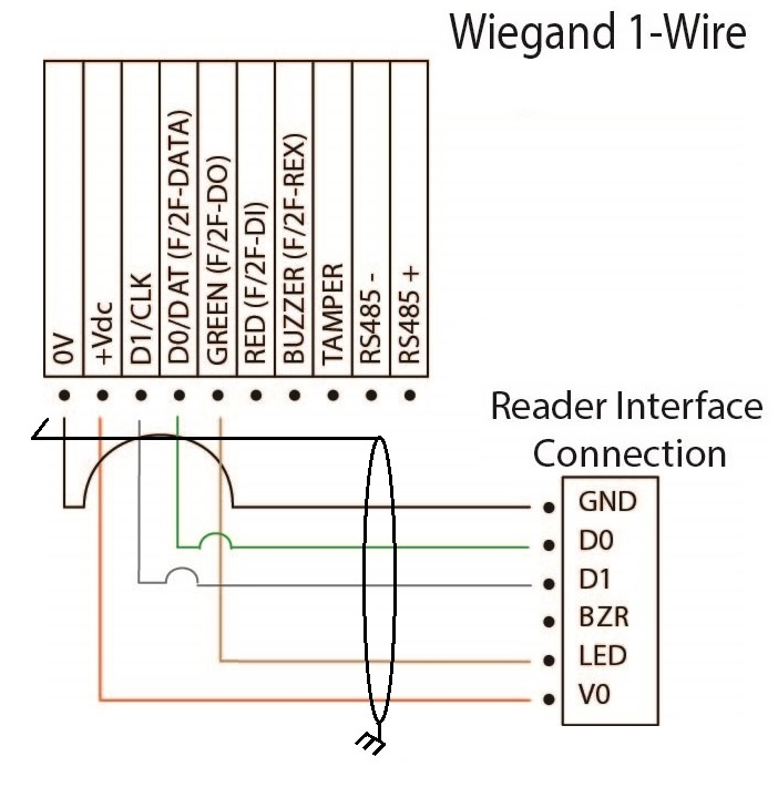
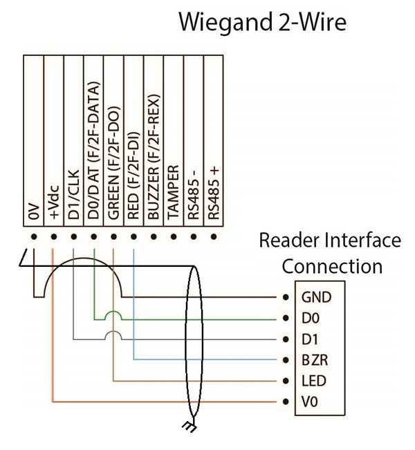
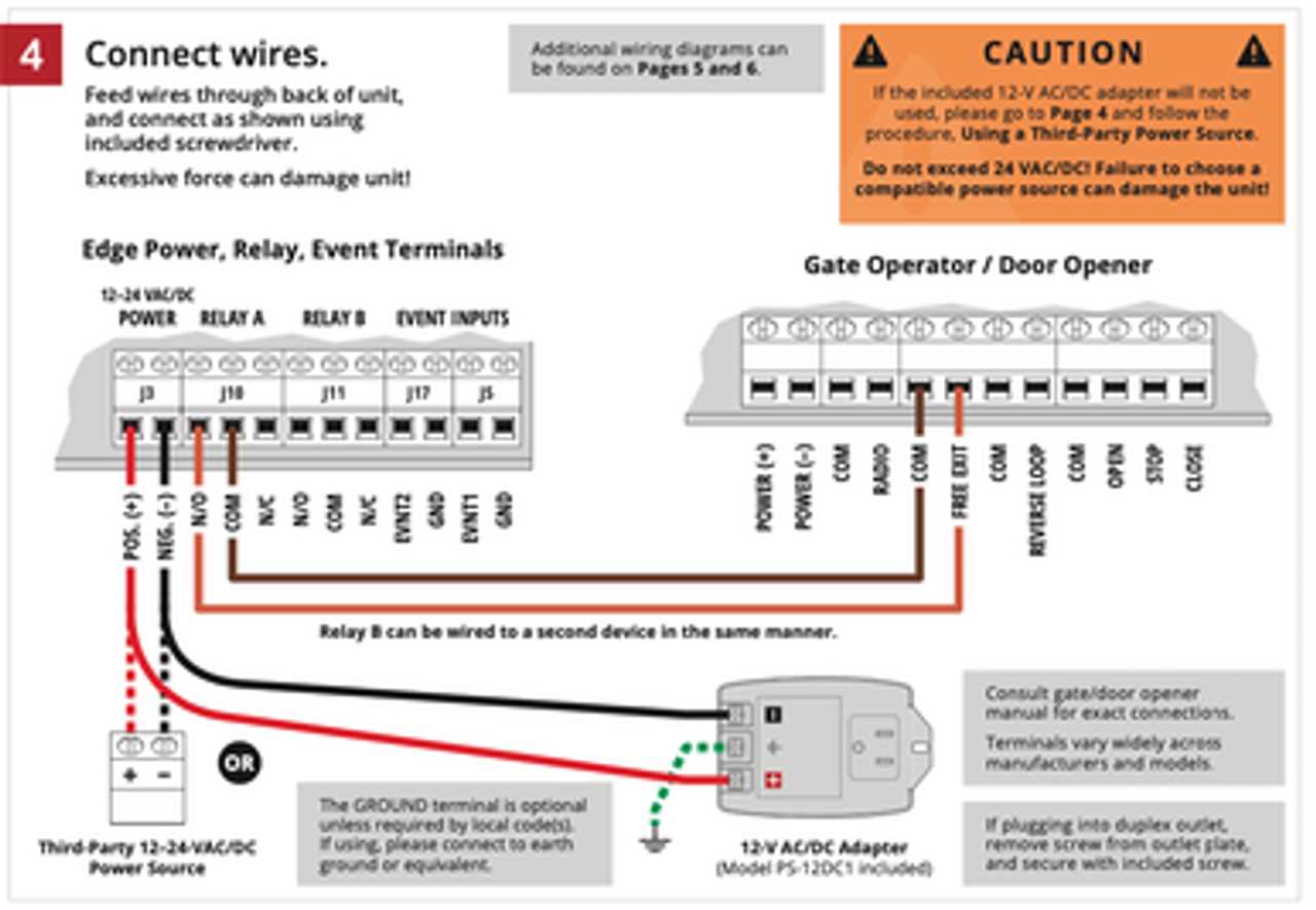
A wiring reader is a technical tool, software interface, or systematic methodology used to interpret complex electrical schematics and trace physical circuit paths across automotive 12V/24V layouts and residential electrical architectures. According to SAE International, adhering to standardized automotive wiring and circuit symbology protocols ensures diagnostic accuracy and prevents catastrophic component failure during system testing. Mastering schematic interpretation transforms abstract lines and nodes into actionable diagnostic pathways, reducing troubleshooting time for home electricians, automotive technicians, and DIY mechanics alike. Grasping the foundational layers of schematic analysis relies heavily on understanding basic mapping techniques detailed within Wiring Diagram Basics.
Wiring Technical Snapshot:
- Core Focus: Systematic decoding of electrical symbols, circuit paths, and terminal designations.
- Target Scope: Automotive 12V DC networks, 24V commercial setups, and residential AC power grids.
- Key Recommendation: Always cross-reference schematic wire color codes with physical wire harness inspections using a digital multimeter.
Core Principles and Detailed Overview
Interpreting a wiring diagram requires a structured approach that correlates schematic symbols with real-world physical conductors, relays, fuses, and loads. A professional wiring reader decodes standardized conventions including international terminal designations, wire gauge size markings, and inline connector pinout numbers. In modern automotive applications, multiplexed wiring networks and Controller Area Network (CAN) bus protocols require rigorous adherence to logical signal tracking rather than simple continuity checks. Similarly, residential installations governed by modern building codes demand precise understanding of hot, neutral, and ground pathways to prevent hazardous faults. Technicians working on specialized subsystems frequently utilize structured layouts found in Vehicle Wiring Diagrams to isolate harness breaks and ground faults.
Key Specifications and Breakdown
| Circuit / Terminal | Standard Wire Color / Gauge | Operational Role & Safety Check |
|---|---|---|
| Automotive Battery Positive | Red / 10 AWG | Delivers continuous direct current from the power source; verify continuity with power disconnected. |
| Automotive Chassis Ground | Black / 12 AWG | Completes the electrical return path to the battery negative terminal; check for resistance under 0.1 ohms. |
| Residential Hot Feeder | Black / 14 AWG | Carries high-voltage alternating current load; verify de-energization using a non-contact voltage tester before servicing. |
Strict adherence to manufacturer schematic standards prevents accidental short-circuiting, thermal overload, and electrical fires during diagnostic procedures. — National Fire Protection Association (NFPA)
Step-by-Step Practical Application and Guidelines
Executing an accurate circuit diagnosis begins by isolating the specific subsystem schematic and locating every connector, splice, and ground point referenced in the diagram. Technicians must first verify the power source and fuse integrity before testing downstream load components. Using a high-impedance digital multimeter, validate voltage drops across switches and relays to pinpoint hidden high-resistance faults. When managing complex auxiliary configurations, cross-referencing documentation within Relay and Component Wiring Diagrams ensures proper trigger wire routing and coil activation sequencing. Systematic documentation of voltage readings during testing prevents redundant diagnostic steps and guarantees complete circuit verification.
Common Challenges and How to Avoid Them
Misinterpreting schematic abbreviations, ignoring wire gauge size changes across connectors, and failing to account for high-resistance corrosion represent the most frequent diagnostic pitfalls. Technicians often misread mirrored connector pinout views, mistaking the wire-side perspective for the component-side perspective and probing the incorrect terminal. Overcoming these errors requires meticulous visual comparison between the physical harness layout and the engineering blueprint. Utilizing structured troubleshooting methodologies available in Wiring Troubleshooting helps isolate intermittent electronic faults and ghost voltages effectively.
💬 Frequently Asked Questions
Explore More Wiring Diagrams and Schematics on ReadWires
Mastering electrical schematics requires access to comprehensive, accurate, and up-to-date documentation across every automotive, marine, and residential application. Professionals and DIY enthusiasts can expand their diagnostic capabilities by exploring thousands of verified schematics, pinouts, and technical guides available through the centralized library at ReadWires.com.
Wiring Diagram Schematics & Details