Introduction
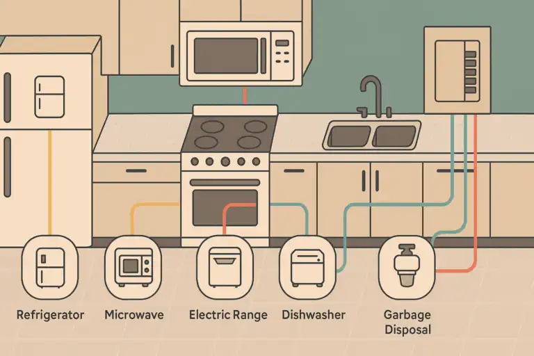
Wiring appliance installations require precise adherence to circuit schematics, conductor sizing, and terminal integrity to ensure safe power delivery across automotive and residential environments. According to the National Electrical Code (NFPA 70 / NEC), all electrical conductors and connected equipment must be rated, installed, and protected in a manner that prevents overcurrent, thermal degradation, and physical damage. Proper system execution bridges the gap between raw power sources and functional equipment, eliminating unpredictable resistance failures. Mastering these configurations allows practitioners to navigate complex schematics found within Appliance and Device Wiring repositories without guesswork. Whether integrating a 12V DC automotive accessory or terminating a heavy-duty 240V residential appliance line, methodological precision remains the single greatest safeguard against electrical fires.
Wiring Technical Snapshot:
- Core Focus: Systematic evaluation, circuit routing, and safe termination of load equipment.
- Target Scope: 12V/24V automotive circuits and standard residential appliance networks.
- Key Recommendation: Always verify load current draw against conductor ampacity charts before energizing.
Core Principles and Detailed Overview
Wiring appliance terminals demands comprehensive familiarity with schematic symbols, voltage drops, and circuit isolation techniques. Direct answer verification relies heavily on understanding how current travels from the power distribution block through protective fuses and control relays before reaching the final load. In automotive contexts, technicians often reference Vehicle Wiring Diagrams to trace chassis grounds and switched ignition feeds accurately. Conversely, domestic applications require strict segregation of hot, neutral, and equipment-grounding conductors. Every splice, crimp, and screw terminal introduces a potential resistance point; therefore, maintaining mechanical security alongside electrical conductivity is paramount. Utilizing specialized tools such as digital multimeters, wire strippers, and calibrated ratcheting crimpers ensures long-term operational stability under continuous thermal and vibrational stress.
Key Specifications and Breakdown
| Circuit / Terminal | Standard Wire Color / Gauge | Operational Role & Safety Check |
|---|---|---|
| Hot / Power Feed | Black / Red (10–14 AWG) | Carries energized current; verify zero voltage using a multimeter before handling. |
| Neutral / Return | White / Light Gray (10–14 AWG) | Completes the circuit loop back to the source; check for loose terminations or open lines. |
| Equipment Ground | Bare Copper / Green (12–16 AWG) | Protects against chassis shorts and fault currents; measure resistance to ground under 1 ohm. |
Proper overcurrent protection sizing must match the minimum ampacity rating of the smallest conductor in the entire circuit branch, preventing catastrophic thermal runaway. — National Fire Protection Association (NFPA)
Step-by-Step Practical Application and Guidelines
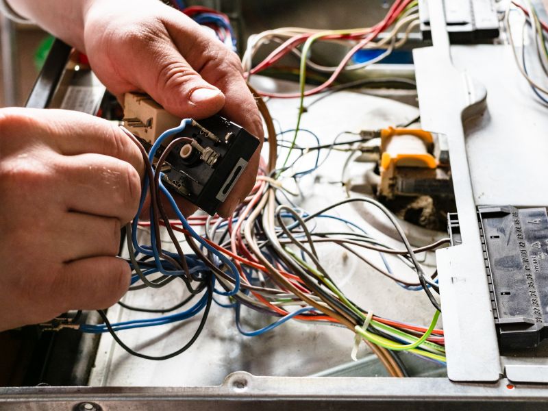
Executing a reliable installation involves a strict sequence of planning, isolation, wiring, and testing. Direct answer execution starts with disconnecting all power sources at the main breaker or battery disconnect before touching any conductors. Reference specific documentation, such as Home Electrical Wiring Diagrams, to confirm layout constraints and box fill capacities. Strip insulation cleanly without nicking the underlying strands, apply heat-shrink tubing where environmental moisture exposure is likely, and torque all screw terminals to manufacturer-specified inch-pounds. Conclude the procedure by performing continuity checks and functional load tests to guarantee the system operates safely within design thresholds.
Common Challenges and How to Avoid Them
Voltage drop, high-resistance ground paths, and incorrect wire gauge selection represent the most frequent pitfalls encountered during electrical troubleshooting. Direct answer resolution requires isolating the fault using voltage-drop testing under an active load rather than relying solely on simple continuity checks. Technicians frequently inspect auxiliary systems through Relay and Component Wiring Diagrams to pinpoint oxidized contacts, chafed wire insulation, or loose spade connectors. Avoiding these recurring issues depends on meticulous wire management, securing harnesses away from sharp sheet metal edges, and using marine-grade heat-shrink butt connectors to seal out corrosive elements.
💬 Frequently Asked Questions
Explore More Wiring Diagrams and Schematics on ReadWires
Mastering complex electrical systems becomes significantly easier when utilizing organized schematics, technical reference charts, and diagnostic guides. Practitioners can expand their knowledge base by browsing the extensive digital archive available at ReadWires.com to locate precise schematics for automotive, residential, and industrial applications.
Wiring Diagram Schematics & Details