Introduction
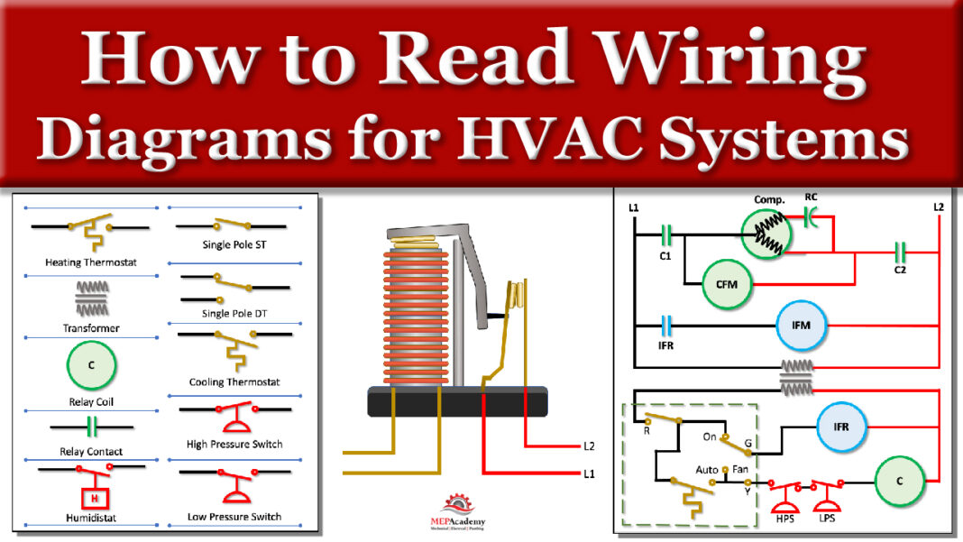
Reading appliance wiring diagrams requires systematically decoding standardized schematic symbols, tracing power distribution paths, and recognizing component interconnections to isolate electrical faults. According to the National Electrical Code (NFPA 70 / NEC), strict adherence to standardized symbology and wire color identification is mandatory for verifying circuit integrity and preventing catastrophic electrical failures during service operations. Mastering Wiring Diagram Basics bridges the gap between complex industrial schematics and practical workbench diagnostics for both residential appliances and complex machinery.
Wiring Technical Snapshot:
- Core Focus: Decoding graphical schematics, terminal designations, and power delivery paths in electrical systems.
- Target Scope: 120V/240V home appliances, industrial electromechanical devices, and auxiliary 12V/24V control loops.
- Key Recommendation: Always verify circuit de-energization with a calibrated digital multimeter before performing continuity checks or component replacement.
Core Principles and Detailed Overview
Appliance schematics function as a graphical roadmap of electricity flow, utilizing standardized symbols for switches, heating elements, motors, and relays to represent physical circuits. Directing attention to the power source reveals how line voltage travels through safety fuses, door interlock switches, and thermostats before reaching inductive or resistive loads. To deepen foundational knowledge across diverse setups, technicians frequently cross-reference data found within Appliance and Device Wiring blueprints. Every line on a diagram indicates a physical conductor, while line intersections marked with dots denote spliced junctions, distinguishing them from simple line crossovers that lack electrical connection. Understanding these conventions ensures accurate tracking of neutral returns, equipment grounding conductors, and low-voltage control loops.
Key Specifications and Breakdown
| Circuit / Terminal | Standard Wire Color / Gauge | Operational Role & Safety Check |
|---|---|---|
| Line / Hot (L1/L2) | Black or Red (12–14 AWG) | Carries high voltage; verify zero potential to ground with a meter. |
| Neutral Return | White or Light Gray (12–14 AWG) | Completes current path; check for loose terminations causing high resistance. |
| Equipment Ground | Bare Copper or Green (12–14 AWG) | Provides fault path; verify continuity to chassis and earth ground. |
Electrical safety requires treating every unverified circuit as live until physically tested and proven de-energized using a calibrated meter verified against a known live source. — National Fire Protection Association (NFPA)
Step-by-Step Practical Application and Guidelines
Executing a systematic diagnostic workflow begins by locating the manufacturer technical sheet, usually tucked behind the front service panel or inside the appliance console. Tracing the schematic requires following the voltage input from the terminal block through protective devices like thermal fuses and overload relays. When components fail to activate, isolating the fault involves measuring voltage drops across closed switches or checking isolated component resistance against manufacturer specifications. For broader diagnostic methodologies applicable to multi-system equipment, review the guides available under Wiring Troubleshooting to refine isolation techniques. Documenting each reading ensures that intermittent mechanical failures, such as a vibrating centrifugal switch in a motor, are caught before replacing expensive control boards unnecessarily.
Common Challenges and How to Avoid Them
Misinterpreting schematic abbreviations, ignoring OEM revision updates, and confusing terminal numbering conventions represent the most frequent pitfalls encountered during electrical diagnostics. Modern appliances frequently integrate solid-state logic boards, making it essential to differentiate between high-voltage power switching and low-voltage sensor inputs. Technicians must also account for auxiliary control modules detailed in resources such as Home Electrical Wiring Diagrams when tracing power back to dedicated branch circuit breakers. Avoiding misdiagnoses requires checking every physical wire harness against the printed legend, as aftermarket replacements or previous repairs may alter factory color codes.
💬 Frequently Asked Questions
Explore More Wiring Diagrams and Schematics on ReadWires
Mastering electrical schematics empowers technicians and DIYers to diagnose, repair, and maintain complex electromechanical systems safely and efficiently. Expanding technical expertise across automotive, residential, and specialized networks ensures readiness for any diagnostic challenge encountered in the field. Access an extensive, professionally cataloged library of schematics and diagnostic guides by visiting ReadWires.com to elevate every upcoming electrical project.
Wiring Diagram Schematics & Details