Introduction
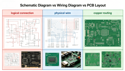
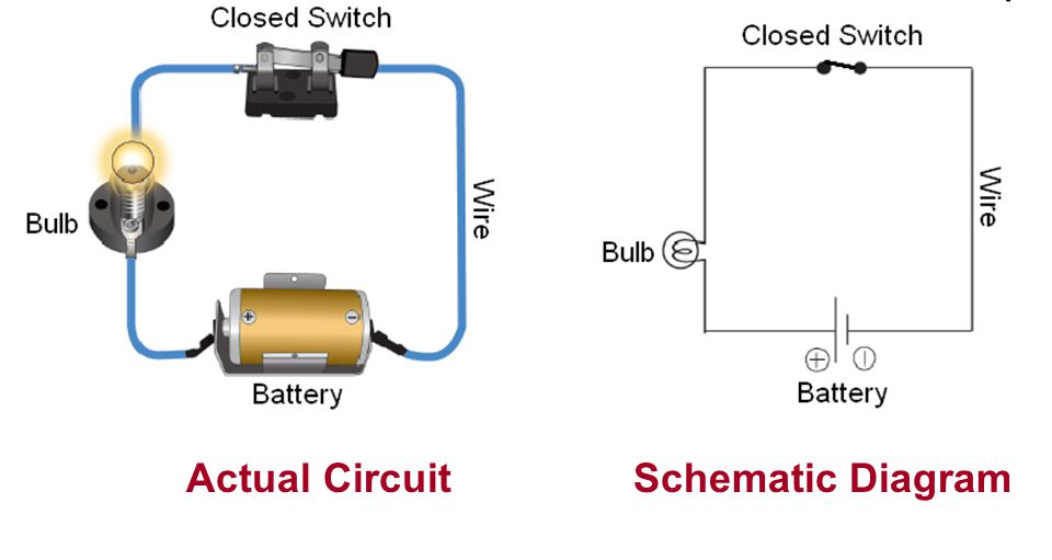
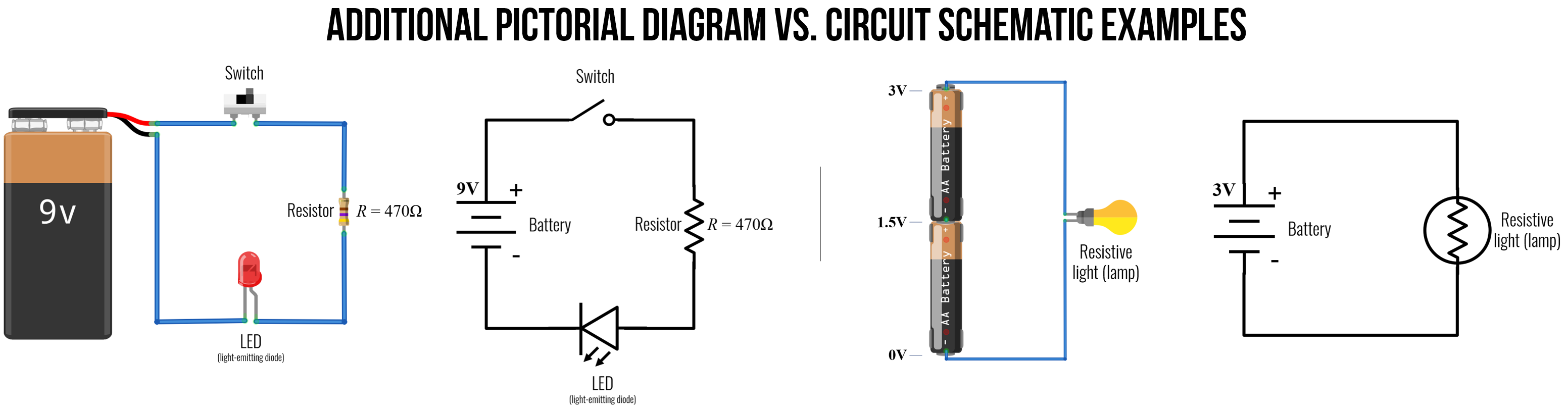
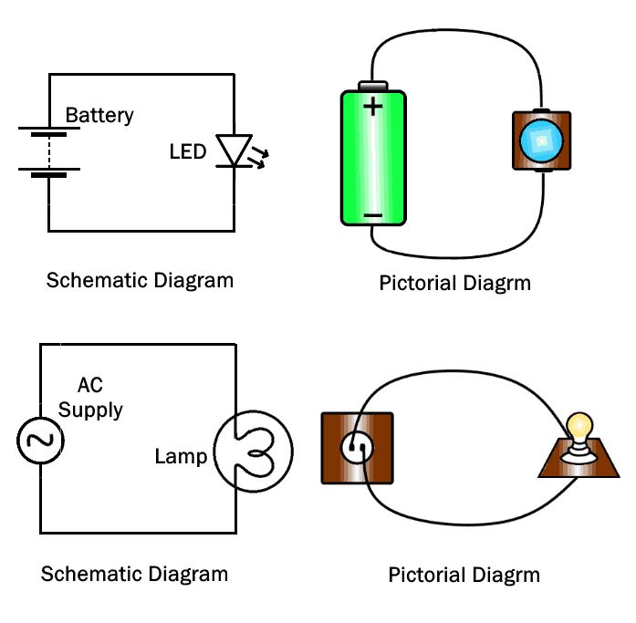
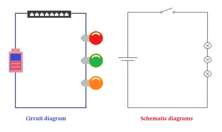
Mastering the difference between wiring diagram & schematic is essential for anyone diagnosing electrical faults in automotive, residential, or industrial systems. A wiring diagram illustrates the physical layout of cables, harnesses, and connectors inside an assembly, whereas a schematic uses abstract symbols to display electrical functionality and signal flow without regard to physical location. Technicians frequently confuse these two technical blueprints during complex fault-finding missions. Knowing when to reference a physical pictorial versus a logical layout saves diagnostic hours and prevents catastrophic misinterpretation of circuits. This distinction proves critical whether tracing a 12V automotive harness or laying out residential Home Electrical Wiring Diagrams.
💡 Technical Key Takeaways:
- Core Focus: Diagnostic schematic and terminal connection layout for Difference Between Wiring Diagram & Schematic.
- Target Scope: Field technicians, automotive DIYers, and residential/commercial electricians.
- Safety Rule: Always disconnect the primary power source/battery terminal and verify zero voltage with a multimeter before touching wires.
Core Concepts and Wiring Fundamentals
Electrical systems rely on closed loops consisting of a power source, conductors, control devices, and loads. In modern 12V and 24V DC automotive environments, power originates at the battery or alternator, flows through protective fuses or fusible links, passes through electromechanical relays and switches, and completes its journey through a load back to a negative chassis ground. Residential and industrial AC systems operate similarly in principle, utilizing hot conductors, circuit breakers, switches, and neutral return paths.
Every physical circuit depends heavily on reliable connectors, splices, and terminal integrity. Resistance increases exponentially at corroded or loose connection points, generating localized heat and voltage drop. Understanding how these physical components interface with Vehicle Wiring Diagrams allows technicians to track voltage from the source to the actuator accurately.
[Electrical fires in residential and commercial structures frequently originate from loose terminal connections, underscoring the critical need for proper torque and physical diagram verification] — [National Fire Protection Association (NFPA)]
Diagram Explanation and Key Components
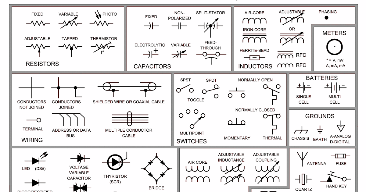
A wiring diagram displays the actual physical routing, connector pin numbers, wire colors, and harness breakout points found on a machine or vehicle. Conversely, a schematic represents electrical logic through standardized symbols, showing how current flows from input to output regardless of where the physical wires run in the chassis or wall. Reading a schematic requires interpreting ANSI, IEC, or SAE graphical symbols for resistors, capacitors, switches, diodes, and relay coils. Wire color codes vary significantly by region; for instance, automotive and electrical standards differ between the US, UK, Canada, and Australia, where local bodies such as the NEC, CEC, BS 7671, and AS/NZS 3000 dictate specific color designations for live, neutral, and protective earth conductors.
When breaking down complex systems, reviewing Wiring Diagram Basics helps beginners bridge the gap between physical terminal blocks and abstract schematic lines. Keeping track of pin identification numbers ensures that a multi-pin connector is never probed backward.
Common Problems and Troubleshooting Methods
Typical electrical faults manifest as open circuits, short circuits to ground, high-resistance connections, and voltage drops caused by corrosion. Diagnostic procedures must always follow a systematic, step-by-step methodology rather than random guessing or part swapping. Begin by verifying the operational status of the primary fuse using a digital multimeter set to continuity or voltage mode. If the fuse is blown, isolate the circuit by disconnecting downstream loads before installing a replacement to prevent immediate re-failure.
Next, utilize a schematic to trace the control and load sides of the circuit, checking for expected voltage at each junction box, relay terminal, or connector pin. Voltage drop testing under an active electrical load remains the most accurate method for identifying high-resistance faults hidden inside wire insulation or crimped terminals. Exploring structured Wiring Troubleshooting guides provides additional frameworks for isolating elusive intermittent faults.
Practical Tips and Safety Considerations
Working with electricity demands rigorous adherence to safety protocols to prevent personal injury, equipment damage, or fire hazards. Always de-energize mains circuits and verify zero energy state with a calibrated multimeter before touching any bare conductor. When servicing vehicles or mobile machinery, disconnect the negative battery terminal and secure it away from accidental contact. Ensure that replacement wires match or exceed the original ampacity, gauge, and temperature rating specified by the manufacturer.
Common field mistakes include misreading connector pinout orientations from a mirror-image perspective and ignoring regional color-coding conventions. Always cross-reference local codes and manufacturer specifications before modifying an installation. For complex home repairs or high-current industrial work, engage a licensed electrician or qualified technician where mandated by regional law.
Conclusion
Comprehending the difference between wiring diagram & schematic transforms a frustrating diagnostic trial into a logical, efficient engineering process. Wiring diagrams show where physical components live in the real world, while schematics reveal how electrical circuits function in theory. Utilizing both documents in tandem ensures accurate testing, proper installation, and long-term electrical safety. Continue exploring technical documentation categories to refine diagnostic skills across diverse applications.
Quick Wiring Specifications & Terminal Guide
| Component / Circuit | Standard Wire Gauge | Recommended Protection |
|---|---|---|
| Control & Trigger Signals | 18 – 20 AWG | 5A – 7.5A Inline Fuse |
| Standard Auxiliary Load | 14 – 16 AWG | 15A – 20A Circuit Breaker |
| Main Power Feed / Supply | 10 – 12 AWG | 30A – 40A Heavy-Duty Relay |
Images References