Introduction
Decoding wire symbols is the essential practice of translating schematic glyphs into physical electrical components across automotive, residential, and industrial systems. Understanding these graphic representations prevents catastrophic misinterpretations that lead to equipment damage, short circuits, or personal injury during installation and repair. This foundational skill underpins every phase of electrical work, allowing technicians and do-it-yourself enthusiasts alike to trace circuits accurately. Navigating a complex schematic without knowing standard symbology wastes valuable diagnostic time and introduces avoidable human error.
💡 Technical Key Takeaways:
- Core Focus: Diagnostic schematic and terminal connection layout for Decoding Wire Symbols.
- Target Scope: Field technicians, automotive DIYers, and residential/commercial electricians.
- Safety Rule: Always disconnect the primary power source/battery terminal and verify zero voltage with a multimeter before touching wires.
Core Concepts and Wiring Fundamentals
Electrical schematics rely on a standardized visual language to represent physical components like wires, fuses, relays, connectors, and power sources. A wire is simply represented by a solid line, but intersecting lines require careful interpretation to distinguish between a connected junction and a mere crossover. Power sources typically appear at the top of a diagram, while ground symbols anchor the return path at the bottom. Fuses and circuit breakers protect these pathways by interrupting current flow during an overload, ensuring the downstream wiring does not overheat.
Control devices such as switches, pushbuttons, and relays dictate how power flows through a circuit. Relays use a low-current control circuit to manage a high-current load circuit, shielding sensitive switches from excessive electrical loads. Connectors appear as matching blocks or multi-pin plug icons that map how distinct wiring harnesses interface with one another. Mastering these physical and graphical relationships bridges the gap between abstract blueprints and hands-on implementation found in Wiring Diagram Basics.
Electrical fires and component failures frequently originate from unverified circuit modifications and incorrect wire sizing — National Fire Protection Association (NFPA)
Diagram Explanation and Key Components
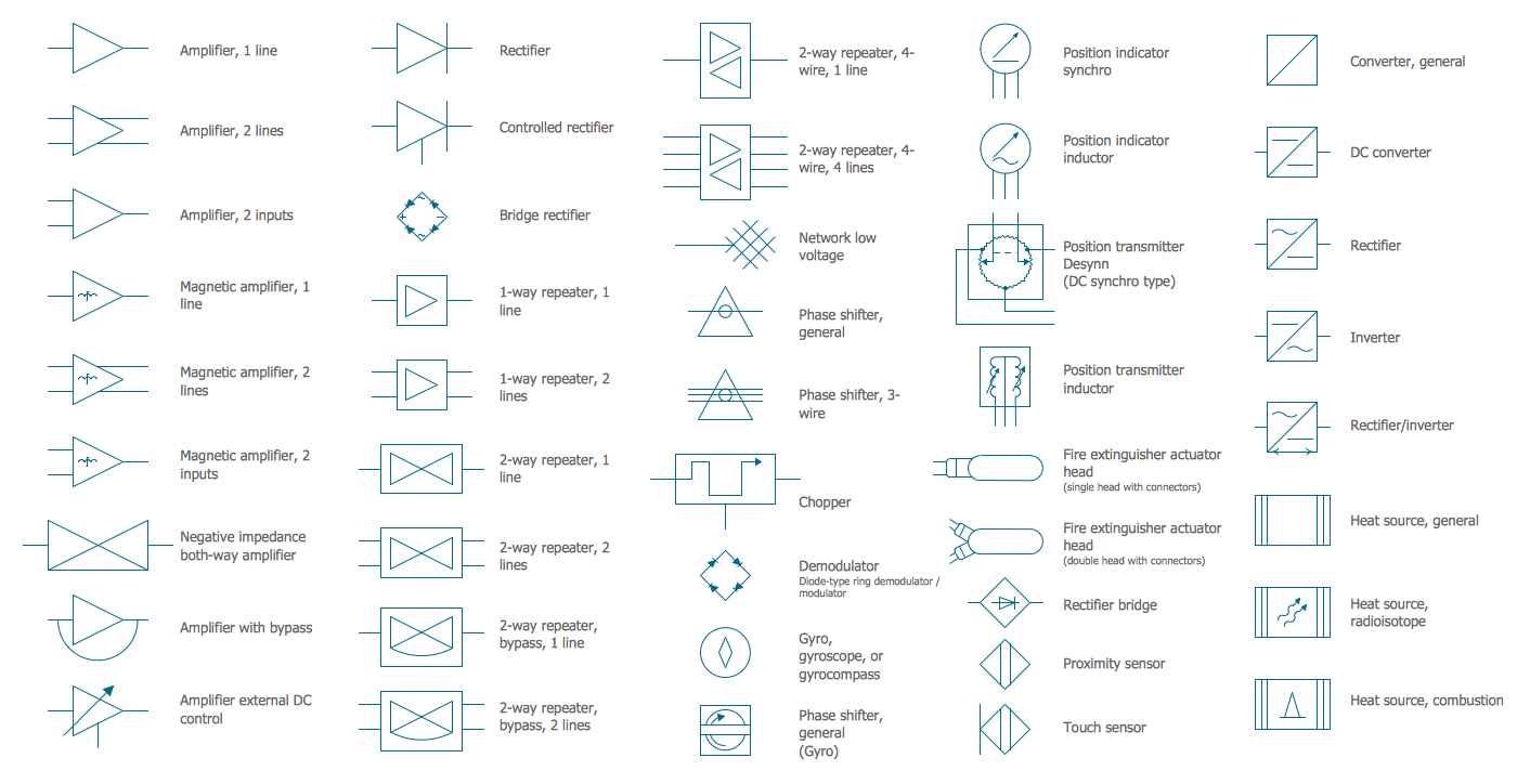
Decoding wire symbols requires recognizing distinct graphical shapes, line weights, and alphanumeric labeling conventions established by governing bodies. Standardized symbology spans industries, though specific interpretations vary between residential building codes and mobile low-voltage architectures. For instance, a wavy line denotes an alternating current source typical of household mains, while parallel lines indicate a direct current battery system found in vehicles. Color codes further clarify circuit function, though regional variations exist between the NEC in the US, the CEC in Canada, BS 7671 in the UK, and AS/NZS 3000 in Australia.
Reading these diagrams also involves tracking line annotations, such as wire gauge numbers, insulation types, and terminal identifiers stamped onto hardware housings. A squiggly line represents a resistor, a pair of offset plates denotes a capacitor, and an arrow intersecting a component signifies variability, such as a potentiometer or adjustable heating element. When dealing with complex automated systems or specialized control boards, cross-referencing these schematics with manufacturer documentation is critical, as detailed in guides on Relay and Component Wiring Diagrams.
Common Problems and Troubleshooting Methods
Systematic fault-finding begins with comparing the physical installation against the schematic to verify that every component matches its designated symbol and location. Typical wiring failures manifest as open circuits, high-resistance ground faults, short circuits to power, and intermittent connections caused by oxidized terminal pins. Technicians diagnose these issues using digital multimeters to measure voltage drops, continuity, and resistance across specific sections of the circuit layout.
When a fuse repeatedly blows, the underlying cause is rarely the fuse itself, but rather an unwanted path to ground somewhere along the load side of the circuit. Isolating the fault requires disconnecting branch circuits methodically until the short disappears, confirming the exact location of the compromised conductor. For more complex diagnostic scenarios involving integrated control networks, reviewing structured fault-isolation workflows found in Wiring Troubleshooting helps streamline the repair process without guesswork.
Practical Tips and Safety Considerations
Working safely on electrical circuits requires de-energizing the system and verifying zero energy state with a calibrated multimeter or non-contact voltage tester before touching any conductors. For automotive and mobile equipment, always disconnect the negative battery terminal to prevent accidental arcing or module damage. Never rely on memory or visual estimates when determining conductor ampacity; consult the applicable regional electrical code or manufacturer specification to ensure proper wire sizing for the intended load.
A common real-world mistake involves joining dissimilar metals or utilizing substandard crimp connectors, which introduces high resistance and localized heating over time. Secure all wiring harnesses away from sharp sheet metal edges, moving mechanical parts, and excessive heat sources using appropriate grommets and nylon cable ties. Where local law, building codes, or structural regulations require licensed intervention, always engage a qualified professional to perform or sign off on the installation.
Conclusion
Decoding wire symbols transforms an intimidating maze of lines and letters into a logical roadmap for successful electrical installation and repair. Diligent adherence to schematic standards ensures that modifications and diagnostics remain precise, repeatable, and safe for everyone involved. Developing this technical literacy empowers practitioners to tackle complex repairs with confidence across diverse electrical environments. Continue expanding technical proficiency by exploring specialized resources like Vehicle Wiring Diagrams to master system-specific schematics.
Quick Wiring Specifications & Terminal Guide
| Component / Circuit | Standard Wire Gauge | Recommended Protection |
|---|---|---|
| Control & Trigger Signals | 18 – 20 AWG | 5A – 7.5A Inline Fuse |
| Standard Auxiliary Load | 14 – 16 AWG | 15A – 20A Circuit Breaker |
| Main Power Feed / Supply | 10 – 12 AWG | 30A – 40A Heavy-Duty Relay |
Images References


