Introduction
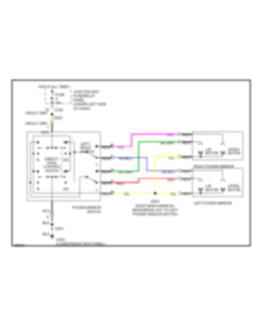
Mastering the f250 electric mirror switch wiring diagram is essential for diagnosing power adjustment and heating faults in heavy-duty truck doors. This document maps out the 12-volt direct current (12V DC) pathways, switch logic, and motor feeds that allow drivers to position exterior mirrors accurately. Heavy-duty utility vehicles operate in demanding environments where moisture intrusion and continuous mechanical vibration frequently compromise electrical integrity. Understanding how these circuits interconnect improves troubleshooting accuracy, prevents unnecessary component replacement, and ensures correct installation procedures across various model years.
💡 Technical Key Takeaways:
- Core Focus: Diagnostic schematic and terminal connection layout for F250 Electric Mirror Switch Wiring Diagram.
- Target Scope: Field technicians, automotive DIYers, and residential/commercial electricians.
- Safety Rule: Always disconnect the primary power source/battery terminal and verify zero voltage with a multimeter before touching wires.
Core Concepts and Wiring Fundamentals
The power mirror system operates on a dedicated 12V DC automotive architecture protected by a centralized cabin fuse block. Voltage originates at the battery, passes through an ignition-switched or accessory-delayed power source, and travels directly to the driver-side master control module or switch assembly. A reversing polarity circuit drives each mirror glass position, utilizing two small internal DC motors per mirror housing—one for horizontal adjustment and one for vertical movement.
Within the door cavity, wires bundle inside a flexible rubber boot spanning the door jamb, a primary stress point for fatigue and wire breakage. The switch itself functions as a multi-pole, double-throw (MPDT) reversing switch. In its resting state, both motor supply lines are tied to a shared ground path. Actuating the toggle directs 12V positive potential to one side of the selected motor while maintaining ground on the opposite side, forcing the internal armature to spin in a specific direction.
Advanced towing mirrors on modern heavy-duty platforms incorporate extra features such as integrated turn signals, clearance lamps, power-folding actuators, and resistance-type heating elements for defrosting. Each feature expands the harness pinout, requiring technicians to reference accurate Vehicle Wiring Diagrams to isolate power feeds from signal lines. Correct ground distribution remains critical, as high-resistance chassis grounds cause intermittent operation of the mirror heaters and motors alike.
[Automotive Electrical Safety] — According to the Society of Automotive Engineers (SAE) standards, low-voltage automotive circuits demand careful circuit protection and proper conductor sizing to prevent excessive voltage drop and thermal overload in accessory harnesses.
Diagram Explanation and Key Components
Interpreting an f250 electric mirror switch wiring diagram requires familiarity with standardized automotive schematic symbols, connector pin callouts, and factory wire color codes. Factory manuals employ standardized alpha-numeric grid systems to track wire paths from the instrument panel fuse box through intermediate door connectors to the mirror motors. A thorough understanding of Wiring Diagram Basics helps technicians trace these complex schematics without misinterpreting line crossings from actual splices.
Schematics typically represent switches in their neutral or unactuated positions. Solid lines indicate primary power distribution, while dashed lines denote optional equipment like power-telescoping functions or heated glass circuits. Terminal identification numbers stamped onto the back of the switch housing correspond directly to the pin designations listed in the service manual legend. Color coding follows standardized automotive conventions governed by regional practices, though stripe tracers often denote secondary circuit functions or specific side assignments.
Pin 1 commonly feeds incoming battery or accessory voltage, while adjacent pins route switched polarity outputs to the left-hand and right-hand mirror assemblies. Ground circuits appear tied to specific chassis grounding points located behind the interior kick panels or door panels. Recognizing these component symbols allows a technician to predict voltage states at every connector before placing a meter probe on a terminal.
Common Problems and Troubleshooting Methods
Systematic diagnostic testing of an unresponsive mirror assembly begins at the easiest access point and follows the flow of electricity toward the load. When an entire mirror function fails, a blown fuse or tripped circuit breaker in the central junction box represents the most frequent root cause. Conversely, when only one axis of movement fails—such as vertical tilt while horizontal adjustment functions normally—the fault usually lies within the switch contacts, the door harness, or the internal motor itself.
Professional diagnosis relies on a digital multimeter set to measure DC voltage and continuity. Probing the input terminal at the switch harness confirms whether operating voltage reaches the control interface. Operating the toggle while monitoring output pins verifies if the internal switch contacts successfully bridge power and ground. If voltage is present at the door harness connector inside the mirror housing but the glass fails to move, the internal actuator motor has likely failed mechanically or electrically.
Field experience reveals that broken copper strands inside the rubber door boot frequently mimic failed switches due to repeated flexing during door opening and closing. Technicians should perform a voltage drop test across suspected wire spans rather than relying solely on basic continuity checks, as a single remaining strand can show continuity while failing to carry the necessary operating current under load. For a broader methodology on tracking down elusive electrical faults, consult resources on Wiring Troubleshooting.
Practical Tips and Safety Considerations
Working on modern vehicle electrical systems mandates strict adherence to safety protocols to prevent accidental short circuits, airbag deployment, or module damage. Always disconnect the negative battery terminal before probing uninsulated harness pins or servicing internal door components where accidental contact with metal structures could cause an arc. Use back-probe pins on multimeter leads rather than piercing wire insulation, as pierced jackets permit moisture entry, leading to green corrosion and future circuit failure.
When repairing damaged harness sections inside the door jamb, solder and marine-grade heat shrink tubing provide a weather-tight, permanent connection superior to standard crimp connectors exposed to environmental moisture. Ensure replacement fuses match the exact amperage rating specified by the manufacturer; installing an oversized fuse creates a severe fire hazard by allowing excessive current to melt harness wiring during a short circuit. Proper wire routing through door boots prevents pinching and guarantees long-term reliability.
Conclusion
Navigating the f250 electric mirror switch wiring diagram successfully transforms a frustrating intermittent electrical issue into a straightforward diagnostic procedure. By systematically checking fuses, verifying switch logic, and inspecting high-stress flex points in the door harness, technicians and DIY enthusiasts alike can restore full functionality to these heavy-duty utility mirrors. Applying disciplined testing methods ensures safe, reliable repairs that withstand demanding daily operating conditions.
Quick Wiring Specifications & Terminal Guide
| Component / Circuit | Standard Wire Gauge | Recommended Protection |
|---|---|---|
| Control & Trigger Signals | 18 – 20 AWG | 5A – 7.5A Inline Fuse |
| Standard Auxiliary Load | 14 – 16 AWG | 15A – 20A Circuit Breaker |
| Main Power Feed / Supply | 10 – 12 AWG | 30A – 40A Heavy-Duty Relay |
Images References