Introduction
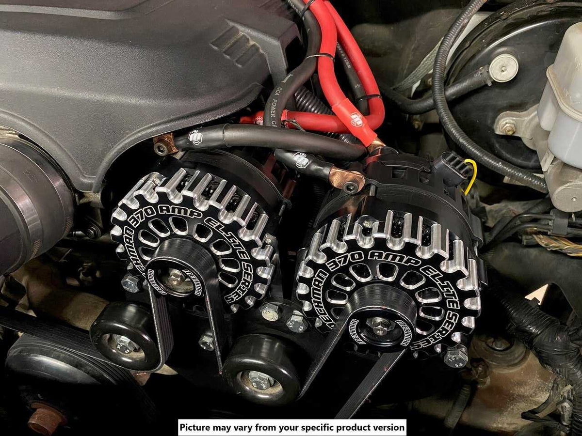
A dual alternator system utilizes two independent generators to meet high electrical demands found in modern specialized vehicles. Modern emergency response units, heavy-duty commercial service trucks, and off-road expedition builds often exceed the capacity of a single factory generator. Understanding how these paired charging units operate prevents catastrophic electrical failures, battery drain, and thermal overload. Mechanics and technicians working on modified or heavy-use platforms frequently encounter dual setups that require precise integration into the primary charging circuit. Proper configuration ensures that auxiliary equipment runs reliably without starving the core engine management computers and safety systems of necessary voltage.
💡 Technical Key Takeaways:
- Core Focus: Diagnostic schematic and terminal connection layout for Dual Alternator System.
- Target Scope: Field technicians, automotive DIYers, and residential/commercial electricians.
- Safety Rule: Always disconnect the primary power source/battery terminal and verify zero voltage with a multimeter before touching wires.
Core Concepts and Wiring Fundamentals
Dual alternator installations involve two distinct generating units driven by the engine crankshaft via serpentine or V-belts. Each alternator functions as an electromechanical device that converts mechanical engine rotation into alternating current, subsequently rectified to direct current for 12V or 24V automotive architectures. Isolators, heavy-duty relays, or smart battery management modules dictate how the output from both generators reaches the battery banks. Wiring requires high-ampacity cables, robust crimped terminal lugs, and secure grounding points to handle continuous high-current loads safely.
Control circuits manage the field excitation for each unit, ensuring they share the electrical load effectively or operate independently based on system design. Parallel configurations combine the output amperage to feed a massive central bus bar, while split setups dedicate one alternator to the chassis and engine loads and the second exclusively to auxiliary gear like winches, inverters, or medical equipment. Reference standard practices outlined in SAE (Society of Automotive Engineers) specifications for proper cable sizing and thermal rating when laying out auxiliary power distribution paths.
[Finding] — According to the Society of Automotive Engineers (SAE), operating auxiliary electrical loads beyond the primary charging system rating without proper parallel isolation significantly increases wiring harness thermal degradation risk.
Diagram Explanation and Key Components
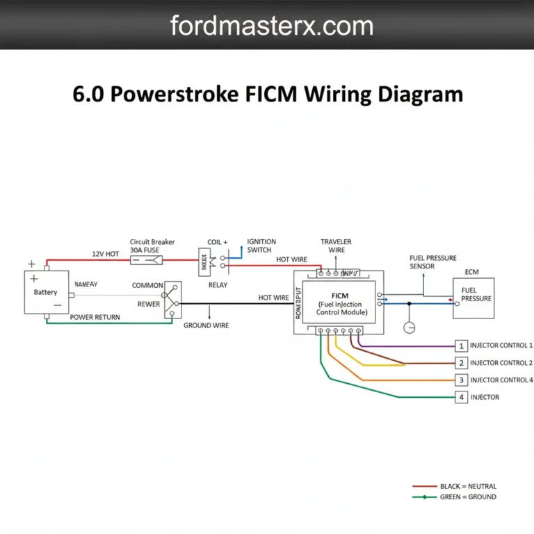
Schematics for a dual alternator system use standardized symbols to illustrate alternators, voltage regulators, sense lines, ignition triggers, and heavy-duty fuses. Reading these diagrams requires attention to line weights, as heavy lines represent high-current power delivery cables while thin lines designate low-current control and signal wires. The primary alternator connects directly to the starting battery and main fuse box, whereas the secondary alternator routes through a dedicated relay, circuit breaker, or DC-to-DC charger before reaching auxiliary battery banks.
Color coding varies significantly by manufacturer and region, making it essential to cross-reference the specific factory documentation or aftermarket kit manual. Technicians must trace the ignition excite wire, voltage sense wire, and battery positive output on both units. Misidentifying the sense wire can lead to overcharging or undercharging conditions that destroy expensive AGM or lithium auxiliary batteries. Detailed wiring blueprints for these complex layouts are often organized within Vehicle Wiring Diagrams to help isolate multi-battery charging paths.
Common Problems and Troubleshooting Methods
Systematic diagnostic procedures for dual charging circuits focus on voltage drop testing, ripple current analysis, and continuity checks across all high-current connections. Typical faults include burnt fusible links, oxidized ground straps between the engine block and chassis, loose belt tension causing slip, and internal diode failure within the secondary alternator. Technicians should never disconnect a battery cable while the engine runs to test an alternator, as voltage spikes can instantly fry sensitive electronic control modules.
Diagnostic testing begins with a digital multimeter to measure resting battery voltage, followed by running voltage checks at both alternator output studs under varying electrical loads. If the secondary alternator fails to output current, the technician must check the excitation circuit signal from the ignition switch or aftermarket controller. For further guidance on identifying multi-path electrical faults, consult resources on Wiring Troubleshooting to streamline the diagnostic workflow.
Practical Tips and Safety Considerations
High-current automotive modifications demand strict adherence to safety protocols, including disconnecting the negative battery terminals before beginning any physical installation work. Working around spinning engine belts and live 12V or 24V power distribution studs requires insulated hand tools and proper personal protective equipment. Installers frequently make the mistake of undersizing the interconnecting cables between the secondary alternator and auxiliary bus bar, which creates a severe fire hazard under sustained heavy loads.
Secure all wiring harness runs away from sharp sheet metal edges, exhaust manifolds, and moving components using rubber grommets and high-temperature split loom. Apply dielectric grease to exposed terminal connections to prevent corrosion from road salt and moisture ingress, especially in marine or off-road applications. For related auxiliary power control circuits and switching logic, reviewing principles found in Relay and Component Wiring Diagrams ensures reliable system operation.
Conclusion
Mastering the installation and maintenance of a dual alternator system empowers technicians and builders to support heavy electrical demands safely and efficiently. Proper component selection, accurate diagram interpretation, and rigorous troubleshooting prevent unexpected field failures. Always verify local standards, use correctly rated overcurrent protection devices, and secure every ground connection to maintain system integrity. Exploring broader electrical documentation via Wiring Diagram Basics provides a solid foundation for handling even the most complex multi-source charging architectures.
Quick Wiring Specifications & Terminal Guide
| Component / Circuit | Standard Wire Gauge | Recommended Protection |
|---|---|---|
| Control & Trigger Signals | 18 – 20 AWG | 5A – 7.5A Inline Fuse |
| Standard Auxiliary Load | 14 – 16 AWG | 15A – 20A Circuit Breaker |
| Main Power Feed / Supply | 10 – 12 AWG | 30A – 40A Heavy-Duty Relay |
Images References