Introduction
A daisy chain lights diagram 3 way connector layout governs how multiple lighting fixtures link together using branched junction hardware in residential, commercial, or mobile environments. Understanding this specific configuration matters because improper bridging or overloading of branched nodes leads to excessive resistance, thermal degradation, and circuit failure. These connection topologies appear frequently in custom architectural illumination, under-cabinet arrays, and specialized vehicle lighting harnesses. Mastering this layout improves safety, streamlines installation quality, and eliminates the guesswork during systematic troubleshooting across different low-voltage and mains-voltage applications.
💡 Technical Key Takeaways:
- Core Focus: Diagnostic schematic and terminal connection layout for Daisy Chain Lights Diagram 3 Way Connector.
- Target Scope: Field technicians, automotive DIYers, and residential/commercial electricians.
- Safety Rule: Always disconnect the primary power source/battery terminal and verify zero voltage with a multimeter before touching wires.
Core Concepts and Wiring Fundamentals
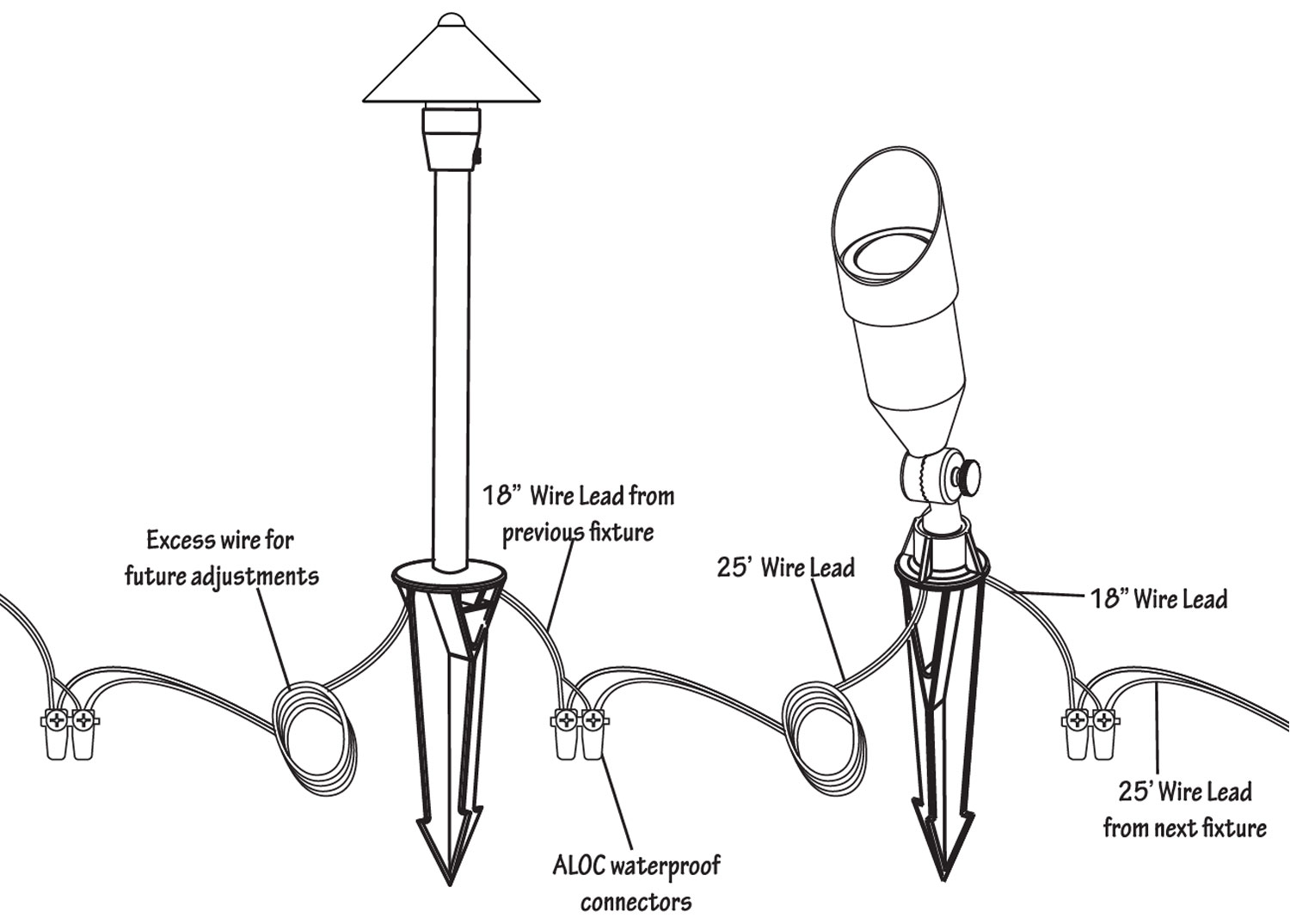
A daisy-chain circuit connects multiple electrical loads in a sequential string, where power flows from the source into the first device, continues through intermediate conductors to the next, and terminates at the final fixture. In standard Home Electrical Wiring Diagrams, this means the live, neutral, and earth conductors enter an enclosure, split via a three-way branching connector, and feed both the local fixture and the downstream run. The three-way connector acts as a physical node where three distinct cable paths converge: the incoming feed, the local drop to the load, and the outgoing feed to the next light in the series.
In low-voltage 12V or 24V DC systems common in automotive or marine setups, these connections handle positive supply, negative return, and sometimes an auxiliary control or signal wire. The physical integrity of the junction dictates the reliability of the entire downstream array. If a mid-circuit three-way connector fails, every fixture downstream loses continuity, turning a localized maintenance task into an extensive tracing exercise.
Improper wire terminations and loose mechanical connections are leading contributors to high-resistance faults in branched electrical circuits. — Electrical Safety Foundation International (ESFI)
Diagram Explanation and Key Components
Reading a daisy chain lights diagram 3 way connector schematic requires recognizing specific symbolic representations for conductors, splice points, and fixture drops. A schematic typically uses continuous lines to denote active conductors, dashed lines for auxiliary signal paths, and distinct nodal dots to show where conductors splice together inside a 3-way distribution block or wire connector. Reviewing Wiring Diagram Basics helps technicians identify how standardized line types separate power circuits from control lines.
Color coding varies significantly by region. In North America under the National Electrical Code (NEC/NFPA 70), 120V residential circuits use black for hot, white for neutral, and bare copper or green for ground. In the UK and Europe under BS 7671, the standard is brown for live, blue for neutral, and green-yellow for earth. In Australia and New Zealand under AS/NZS 3000, active is brown, neutral is light blue, and earth is green-yellow. Automotive DC systems diverge further, typically using red for positive and black or brown for negative ground return. The three-way connector itself must be rated for the specific operating voltage and maximum continuous current drawn by all downstream loads combined.
Common Problems and Troubleshooting Methods
Diagnosing a failing daisy-chain lighting circuit involves methodical voltage drop testing, continuity checks, and physical inspection of every three-way junction node. Typical failure points include loose screw terminals inside junction boxes, oxidized push-in wire connectors, and pinched insulation causing intermittent short circuits to ground. Technicians encountering persistent behavioral issues often consult specialized Wiring Troubleshooting procedures to isolate intermittent faults efficiently.
When the final light in a daisy chain flickers or fails completely, the diagnostic process begins at the last functioning three-way connector rather than the power source. Using a digital multimeter set to continuity or voltage mode, a technician verifies whether power successfully traverses the incoming terminals to the outgoing feed. If voltage is present at the node but the local light remains dark, the fault lies within the fixture drop or its immediate terminal block. Conversely, if voltage drops to zero across the three-way connector, the upstream conductor feeding that node requires inspection.
Practical Tips and Safety Considerations
Mains-voltage installations and high-current vehicle systems demand strict adherence to safety protocols to prevent personal injury and electrical fires. Before touching any conductor, de-energize the circuit at the main breaker panel or disconnect the battery negative terminal, then verify zero energy state using a calibrated voltage tester. Never exceed the ampacity rating stamped on the three-way connector or junction housing. Overloading a daisy chain by adding too many fixtures beyond the manufacturer’s specified maximum run length leads to severe thermal overload and insulation breakdown.
Strip wire insulation to the exact length specified by the connector manufacturer to prevent exposed copper from contacting adjacent terminals or grounded metal enclosures. Torque all mechanical screw terminals to specified foot-pounds or inch-pounds where applicable, as loose connections generate localized heat under heavy loads. Always consult a licensed electrician or qualified technician when local building regulations or insurance policies require formal certification for permanent wiring modifications.
Conclusion
Mastering the daisy chain lights diagram 3 way connector configuration ensures reliable power distribution and reduces the likelihood of catastrophic circuit failures. Proper identification of regional color codes, strict adherence to load limits, and systematic diagnostic workflows keep electrical systems operating safely over their intended service life. Diligent preparation and respect for fundamental electrical principles remain the cornerstones of successful installation and maintenance across all residential, commercial, and mobile environments. Explore additional system designs by reviewing comprehensive Vehicle Wiring Diagrams.
Quick Wiring Specifications & Terminal Guide
| Component / Circuit | Standard Wire Gauge | Recommended Protection |
|---|---|---|
| Control & Trigger Signals | 18 – 20 AWG | 5A – 7.5A Inline Fuse |
| Standard Auxiliary Load | 14 – 16 AWG | 15A – 20A Circuit Breaker |
| Main Power Feed / Supply | 10 – 12 AWG | 30A – 40A Heavy-Duty Relay |
Images References