Introduction
A 7 pin lawn mower ignition switch schematic diagram maps out the complex electrical pathways connecting a modern riding mower’s power source, safety interlocks, starter solenoid, and accessory circuits. Understanding this specific control architecture matters because modern lawn tractors rely on intricate multi-pole switches to prevent accidental engine starts while operators are dismounted. Mastering these schematics significantly improves troubleshooting accuracy, ensures safe maintenance practices, and reduces the risk of expensive electrical component damage during repairs. These configurations typically appear on mid-to-high-end garden tractors equipped with electric Power Take-Off (PTO) clutches, headlights, and extensive operator presence sensing systems. Reviewing related reference material found under Vehicle Wiring Diagrams provides additional insight into standard 12-volt DC switching topologies common in small outdoor power equipment.
💡 Technical Key Takeaways:
- Core Focus: Diagnostic schematic and terminal connection layout for 7 Pin Lawn Mower Ignition Switch Schematic Diagram.
- Target Scope: Field technicians, automotive DIYers, and residential/commercial electricians.
- Safety Rule: Always disconnect the primary power source/battery terminal and verify zero voltage with a multimeter before touching wires.
Core Concepts and Wiring Fundamentals
Small-engine electrical systems operate on a direct current (DC) circuit powered by a 12-volt battery and an engine-driven alternator or stator. The ignition switch acts as a central hub, routing battery voltage to various loads depending on the physical rotational position of the key. Standard operational positions include Off, Run, Lights, and Start, each closing distinct internal contact sets to energize specific circuits.
Beneath the dashboard, the wiring harness bundles multiple insulated conductors that connect the switch terminals to downstream components. These circuits include the main ignition feed, starter solenoid trigger wire, battery charging circuit, magneto ground for engine kill, and accessory feeds for lighting or electric deck engagement. A fuse—typically rated between 15 and 30 amperes depending on the specific tractor model—protects the main charging and accessory circuits from overcurrent events and short circuits.
Safety interlock switches form a crucial part of this ecosystem. These normally open or normally closed switches monitor the operator’s seat, brake pedal, and PTO lever. The 7 pin ignition switch schematic diagram integrates these interlocks to interrupt the starter solenoid control circuit or ground the ignition magneto, preventing the engine from cranking unless all safety parameters are met.
[Finding] — According to the Consumer Product Safety Commission (CPSC), bypasses of safety interlock systems on lawn care machinery contribute significantly to preventable laceration and rollover injuries annually.
Diagram Explanation and Key Components
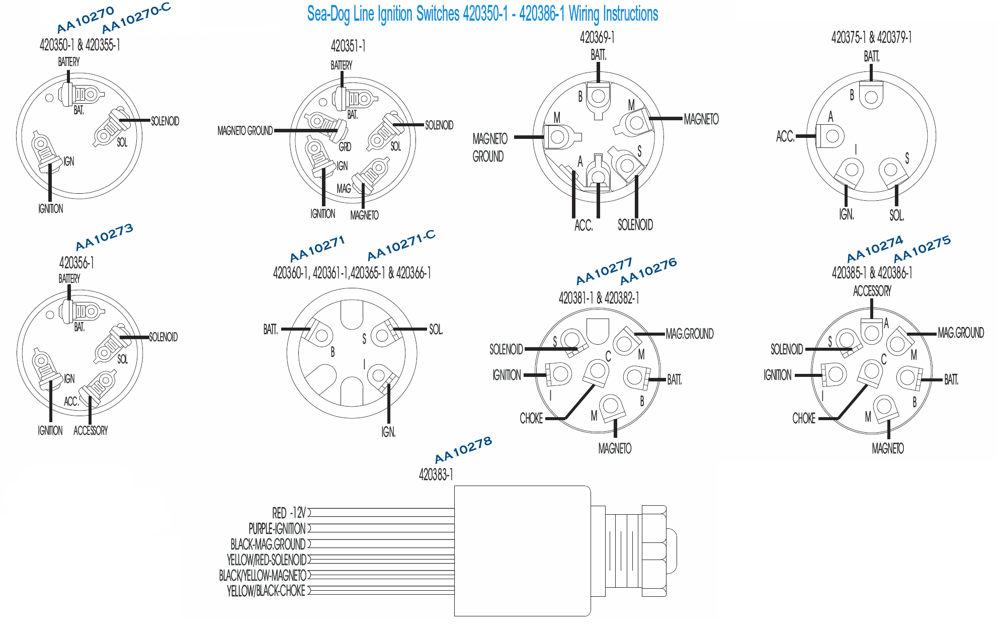
A 7 pin lawn mower ignition switch schematic diagram uses standardized symbols, terminal designations, and line paths to illustrate complex internal switch continuity. Reading these diagrams requires a firm grasp of terminal labeling conventions established by manufacturers and industry groups like the Society of Automotive Engineers (SAE). Common terminal marks found on a seven-terminal rotary switch include B (Battery), S (Starter), M (Magneto/Ignition Ground), A or ACC (Accessory), L (Lights), G (Ground), and I (Ignition power).
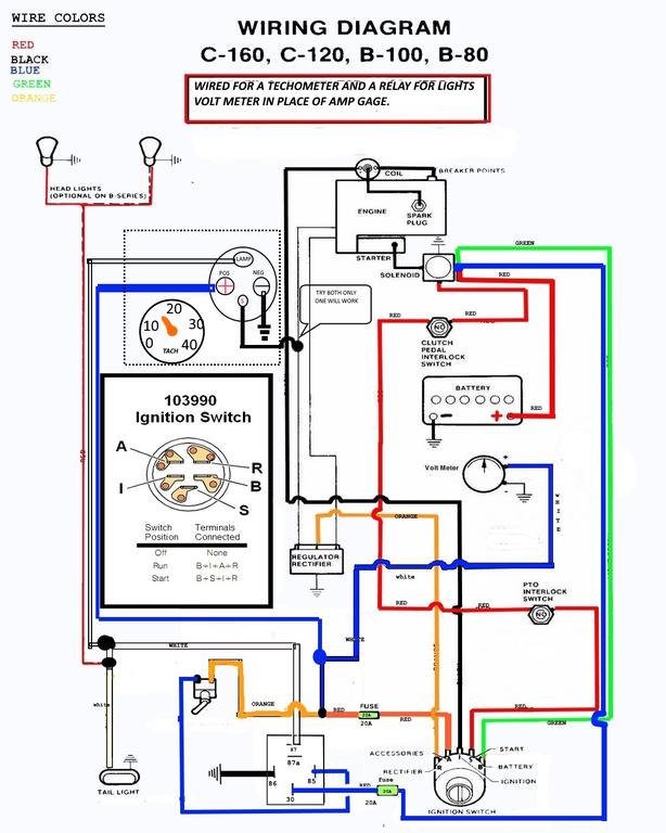
The schematic typically includes a continuity grid or truth table adjacent to the main drawing. This table outlines which terminals maintain electrical continuity in each key position. For instance, in the “Start” position, the battery terminal (B) connects internally to both the starter terminal (S) and the ignition power terminal (I), while the magneto ground (M) is lifted to allow spark generation.
Wire color coding varies substantially by region and equipment manufacturer. North American machines often utilize red for battery positive, yellow or white with a stripe for starter control, and black for ground circuits. European and UK models complying with ISO standards may use alternate color identifiers. Always verify specific wire paths using the equipment manufacturer’s service manual rather than relying strictly on wire color alone.
Common Problems and Troubleshooting Methods
Troubleshooting electrical faults on a multi-pole ignition switch requires a systematic diagnostic approach utilizing a digital multimeter set to measure DC voltage and resistance (ohms). Typical failures include internal contact corrosion caused by moisture exposure, mechanical wear of the spring-loaded detents inside the switch body, and melted housings resulting from excessive current draw or improper aftermarket accessory wiring.
Begin the diagnostic process by disconnecting the negative battery cable to prevent accidental short circuits. Next, inspect the plastic multi-plug connector attached to the rear of the ignition switch for signs of thermal degradation, loose terminal pins, or green copper corrosion. Using the schematic, back-probe the harness connector to verify that input voltage is present at the battery (B) terminal.
To test the switch itself, remove it completely from the dashboard and use a multimeter continuity function across the specified terminal pairs for each key position, cross-referencing the manufacturer’s truth table. If continuity fails to match the diagram specifications in any position, replace the switch assembly. Further guidance on methodical fault-finding techniques is available through Wiring Troubleshooting resources.
Practical Tips and Safety Considerations
Maintaining and repairing low-voltage DC machinery demands strict adherence to safety protocols and neat workmanship. Always disconnect the battery before unbolting dash components or probing live circuits to prevent inadvertent arcing that can weld tools to metal frames or damage sensitive solid-state modules. When replacing damaged wire terminals, use proper ratcheting crimp tools rather than standard pliers to ensure secure, gas-tight mechanical connections that resist vibration.
Applying a small amount of dielectric grease to the ignition switch connector terminals prevents moisture intrusion and subsequent oxidation during outdoor storage. Ensure replacement wire gauge matches or exceeds the original factory specification—typically 12 AWG to 16 AWG for primary power feeds—to prevent dangerous voltage drops and excessive heat generation. Mechanics must also consult regional electrical codes and manufacturer instructions when performing complex modifications. For additional insight into component layout, review standard practices outlined in Relay and Component Wiring Diagrams.
Conclusion
Interpreting a 7 pin lawn mower ignition switch schematic diagram bridges the gap between mechanical frustration and successful, efficient equipment repair. By systematically analyzing terminal continuity, understanding interlock integration, and utilizing proper diagnostic tools, technicians can isolate faults quickly without resorting to costly trial-and-error part replacements. Safety remains paramount throughout any electrical service procedure, requiring disciplined battery disconnection and careful terminal verification. Applying these structured technical principles ensures long-term reliability and safe operation for all types of outdoor power machinery.
Quick Wiring Specifications & Terminal Guide
| Component / Circuit | Standard Wire Gauge | Recommended Protection |
|---|---|---|
| Control & Trigger Signals | 18 – 20 AWG | 5A – 7.5A Inline Fuse |
| Standard Auxiliary Load | 14 – 16 AWG | 15A – 20A Circuit Breaker |
| Main Power Feed / Supply | 10 – 12 AWG | 30A – 40A Heavy-Duty Relay |
Images References