Introduction
A 30 amp service for enclosed trailer installations provides a robust alternating current (AC) power supply capable of running heavy loads like air conditioners, tool chargers, and entertainment centers simultaneously. This electrical setup bridges the gap between basic automotive direct current (DC) systems and stationary grid power, turning a simple cargo box into a functional mobile workshop, race trailer, or camper. Understanding the underlying electrical topology prevents catastrophic overloads, mitigates fire risks, and ensures safe operation whether connected to a campsite pedestal, a home generator, or a dedicated garage outlet. Field experience shows that improper circuit planning remains the leading cause of premature breaker trips and melted shore power inlets in mobile builds.
💡 Technical Key Takeaways:
- Core Focus: Diagnostic schematic and terminal connection layout for 30 Amp Service For Enclosed Trailer.
- Target Scope: Field technicians, automotive DIYers, and residential/commercial electricians.
- Safety Rule: Always disconnect the primary power source/battery terminal and verify zero voltage with a multimeter before touching wires.
Core Concepts and Wiring Fundamentals
Delivering a reliable 30 amp service for enclosed trailer environments requires a balanced combination of shore power inlets, heavy-gauge conductors, and a dedicated distribution panel equipped with main circuit breakers. Shore power refers to external AC electricity brought into the vehicle via a heavy-duty flexible cord connected to a specialized receptacle. Ampacity, which defines the maximum current a conductor can carry continuously without exceeding its temperature rating, dictates that 10-gauge copper wire is the minimum standard for a 30-ampere 120-volt AC circuit in most jurisdictions.
The standard NEMA TT-30 configuration (National Electrical Manufacturers Association Travel Trailer 30-amp configuration) utilizes a three-prong plug containing one 120-volt hot wire, one neutral wire, and one dedicated earth ground. Unlike residential 240-volt split-phase systems, standard trailer hookups rely strictly on a single 120-volt leg rated for 3,600 total watts of continuous power. Overloading this single leg causes thermal stress at the plug blades and breaker trips inside the power center.
Voltage drop must also be factored into long exterior cable runs. When power travels through extended extension cords from a power source to the trailer inlet, resistance in the copper wire reduces the actual voltage reaching internal appliances. Technicians consult established guidelines found in regional electrical standards, such as the NFPA 70 (National Electrical Code) in the United States, the Canadian Electrical Code (CEC) in Canada, BS 7671 in the UK, or AS/NZS 3000 in Australia, to determine proper wire sizing, conduit fill, and overcurrent protection requirements.
Electrical safety data highlights that misuse of extension cords and overloaded temporary power setups are leading contributing factors in mobile property fires, emphasizing the necessity of properly rated permanent inlets and breakers. — Electrical Safety Foundation International (ESFI)
Diagram Explanation and Key Components
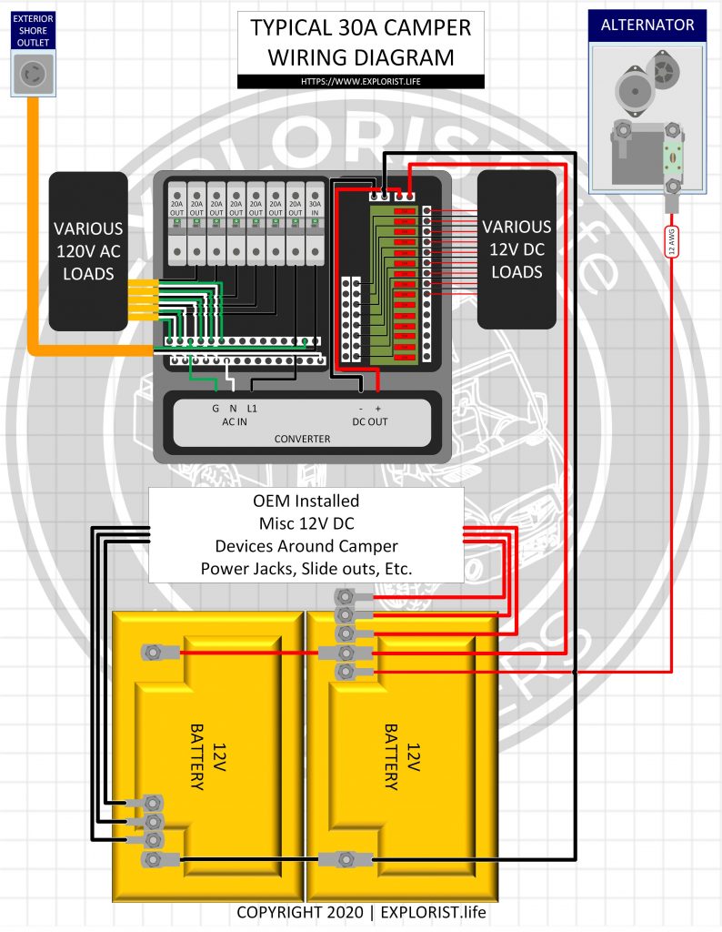
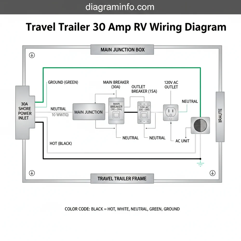
Interpreting schematics for a 30 amp service for enclosed trailer projects requires recognizing standard schematic symbols for circuit breakers, neutral bars, ground buses, and transfer switches. A wiring diagram typically begins with the exterior male receptacle, tracking power through a main molded case circuit breaker directly into a breaker sub-panel. From there, individual branch circuit breakers divide the power to interior receptacles, lighting, and specialized Appliance and Device Wiring.
Color coding varies significantly by region, creating a critical hazard point for international builders or imported equipment. In North America (US and Canada), 120-volt AC wiring uses black for hot, white for neutral, and bare copper or green for ground. In contrast, the UK and Australia (adhering to harmonized European standards or AS/NZS) typically use brown for live (hot), blue for neutral, and green-with-yellow-stripe for earth ground. Technicians must never rely solely on wire color without verifying continuity and circuit function with a digital multimeter.
Circuit breakers protect the physical copper conductors rather than the plugged-in devices. If a high-draw compressor or heater attempts to pull more than 30 amperes through the main feed, the thermal-magnetic trip mechanism inside the breaker opens the circuit. Supplementary automotive-style DC systems inside the trailer often interface with this AC infrastructure through a power converter/charger, which steps down 120-volt AC into 12-volt DC to run interior LED lighting and charge auxiliary batteries, a relationship frequently detailed in comprehensive Vehicle Wiring Diagrams.
Common Problems and Troubleshooting Methods
Systematic fault-finding when establishing or repairing a 30 amp service for enclosed trailer setups involves isolating AC mains power, utilizing visual inspections, and performing voltage drop tests under load. Before touching any terminal, de-energize the system completely, disconnect the shore power cord, and verify zero voltage using a calibrated digital multimeter set to AC volts. Technicians must remember that mains voltage can cause severe injury or death.
A frequent failure point is loose terminal screw connections inside the main breaker panel or behind the exterior shore power inlet. High resistance at these loose junctions generates intense localized heat, resulting in discolored plastic, melted receptacles, and intermittent power drops. Another common issue involves open neutral faults, which can dangerously float the voltage on 120-volt circuits and fry sensitive electronic equipment connected inside the trailer.
When troubleshooting a tripping breaker, technicians disconnect all external loads, reset the breaker, and reconnect appliances one by one while monitoring current draw with a clamp meter. If the breaker trips immediately upon plugging in a specific device, diagnosis points toward an internal short circuit within that appliance rather than a fault in the trailer fixed wiring. For complex multi-battery and inverter tie-ins, reviewing reference materials like Relay and Component Wiring Diagrams helps clarify how automatic transfer switches handle dual power inputs.
Practical Tips and Safety Considerations
Best practices dictate that all high-current AC wiring inside a metal-framed cargo trailer must be protected against physical abrasion by running conductors through flexible non-metallic conduit or secure Romex-style clamps. Because vehicle vibrations constantly stress mechanical connections, using ring terminals with star washers, applying thread-locking compounds where appropriate, and using torque screwdrivers on breaker lugs prevents loose terminations over thousands of miles of transit. Ground fault circuit interrupters (GFCI) must be installed on all receptacle circuits located near water sources or exterior access points to protect users from shock hazards.
A major mistake made during DIY installations is failing to bond the trailer frame to the electrical earth ground system properly, or conversely, creating a ground loop by incorrectly bonding neutral and ground at sub-panels instead of relying solely on the main service pedestal bond. Local regulations dictate whether a licensed electrician or qualified technician must perform or sign off on mains-voltage installations; compliance with local codes is mandatory for insurance validity and personal safety. For those expanding their mobile electrical knowledge into related fields, exploring resources on Audio and Entertainment Wiring Diagrams provides additional insight into managing clean power and avoiding ground hums in mobile enclosures.
Conclusion
Mastering the design, installation, and maintenance of a 30 amp service for enclosed trailer builds ensures reliable, safe power delivery for any mobile application. Adhering to strict conductor sizing rules, respecting regional color-code variations, and performing rigorous diagnostic checks before energizing the system protects both equipment and operators. Diligent maintenance and proper component selection transform a standard utility trailer into a safely powered, professional-grade workspace on wheels.
Quick Wiring Specifications & Terminal Guide
| Component / Circuit | Standard Wire Gauge | Recommended Protection |
|---|---|---|
| Control & Trigger Signals | 18 – 20 AWG | 5A – 7.5A Inline Fuse |
| Standard Auxiliary Load | 14 – 16 AWG | 15A – 20A Circuit Breaker |
| Main Power Feed / Supply | 10 – 12 AWG | 30A – 40A Heavy-Duty Relay |
Images References