Introduction
A wiring diagram for a 12 v four wire relay serves as the essential blueprint for controlling high-current automotive and mobile electrical accessories safely using low-current switches. Mastering this schematic ensures that auxiliary lights, fuel pumps, cooling fans, and custom accessories operate reliably without melting dashboard switches or overloading delicate control circuits. This configuration forms a foundational building block frequently explored within Relay and Component Wiring Diagrams, providing technicians and hobbyists with a dependable method for isolating heavy electrical loads.
💡 Technical Key Takeaways:
- Core Focus: Diagnostic schematic and terminal connection layout for Wiring Diagram For A 12 V Four Wire Relay.
- Target Scope: Field technicians, automotive DIYers, and residential/commercial electricians.
- Safety Rule: Always disconnect the primary power source/battery terminal and verify zero voltage with a multimeter before touching wires.
Core Concepts and Wiring Fundamentals
A standard four-wire automotive relay operates on the principle of electromagnetic induction, utilizing a low-power control circuit to mechanically close a heavy-duty load circuit. Inside the housing, a fine coil of wire creates a magnetic field when energized, pulling a movable contact arm closed to complete the high-amperage path.
Understanding this hardware requires separating the system into two distinct loops: the control side and the load side. The control side handles minimal current from a dashboard switch, ignition source, or electronic control module, while the load side manages the heavy current flowing directly from the battery to the powered device. Fuses must always protect the load supply wire near the power source to prevent catastrophic wire harness damage during a dead short to ground.
[Finding] — According to the Society of Automotive Engineers (SAE) standard J1290, electrical distribution systems in vehicles must incorporate properly rated overcurrent protection devices as close to the power source as physically possible to mitigate thermal overload risks.
Diagram Explanation and Key Components
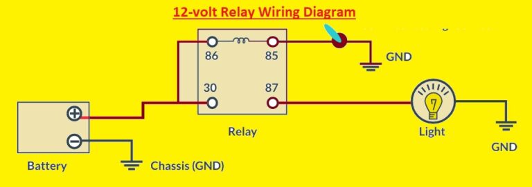
Reading a wiring diagram for a 12 v four wire relay requires recognizing the standardized numbering system stamped onto the bottom of the relay housing or depicted on schematic symbols. These terminal numbers establish exact connection points for the control and load circuits regardless of manufacturer variations.
Terminal 30 connects directly to the fused battery power supply, feeding the main load contact. Terminal 87 routes outgoing power from the relay switch to the actual accessory, such as a driving light or electric motor. Terminal 85 receives the switched signal or ignition trigger to activate the internal electromagnet coil. Terminal 86 provides the return path or chassis ground to complete the coil circuit. Schematics illustrate these pathways using distinct line weights, where thick lines represent high-current carrying conductors and thin lines denote low-current control wires. Wire colors vary significantly across international regions due to different manufacturing standards, making multimeter verification more reliable than relying solely on jacket color.
Common Problems and Troubleshooting Methods
Systematic fault-finding on relay circuits prevents unnecessary component replacement and slashes diagnostic time in the field. Typical failures include internal coil open-circuits, corroded relay sockets, high-resistance oxidized terminal pins, and compromised chassis grounds that starve the electromagnetic coil of adequate return current.
Diagnosis begins with a visual inspection of the fuse and relay terminals for signs of thermal discoloration or moisture intrusion. Technicians then deploy a digital multimeter set to DC voltage to verify battery positive potential at Terminal 30. Actuating the control switch while probing Terminal 85 confirms whether the trigger voltage reaches the coil. If the coil receives power and ground but Terminal 87 fails to output voltage, the internal contacts have welded open or burned out, necessitating relay replacement. Mechanics frequently encounter intermittent operation caused by loose female spade connectors inside the relay socket, which require proper tensioning or replacement to ensure solid mechanical contact.
Practical Tips and Safety Considerations
Implementing robust installation practices guarantees long-term durability and protects mobile electrical systems from environmental degradation. Technicians must disconnect the vehicle battery before cutting, stripping, or crimping heavy power cables to prevent accidental arcing against grounded chassis components.
Selecting appropriate wire gauge sizes based on total circuit amperage and wire length prevents excessive voltage drop. Heat-shrink tubing with adhesive lining provides superior environmental sealing against moisture and road salt compared to standard electrical tape, especially in under-hood applications. Furthermore, mounting relays with the terminal pins facing downward or sideways prevents water accumulation inside the plastic housing. For more complex accessory integrations, consulting references found within Vehicle Wiring Diagrams helps maintain clean, professional routing habits that comply with recognized industry standards.
Conclusion
Decoding a wiring diagram for a 12 v four wire relay transforms a confusing bundle of colored cables into a logical, manageable electrical system. By separating low-current control triggers from high-current power delivery, builders protect sensitive switches and enhance overall circuit reliability. Diligent fuse placement, secure terminal connections, and methodical diagnostic procedures ensure that auxiliary electrical installations perform safely for years to come. Additional foundational knowledge for broader electrical projects remains accessible through Wiring Diagram Basics.
Quick Wiring Specifications & Terminal Guide
| Component / Circuit | Standard Wire Gauge | Recommended Protection |
|---|---|---|
| Control & Trigger Signals | 18 – 20 AWG | 5A – 7.5A Inline Fuse |
| Standard Auxiliary Load | 14 – 16 AWG | 15A – 20A Circuit Breaker |
| Main Power Feed / Supply | 10 – 12 AWG | 30A – 40A Heavy-Duty Relay |
Images References