Introduction
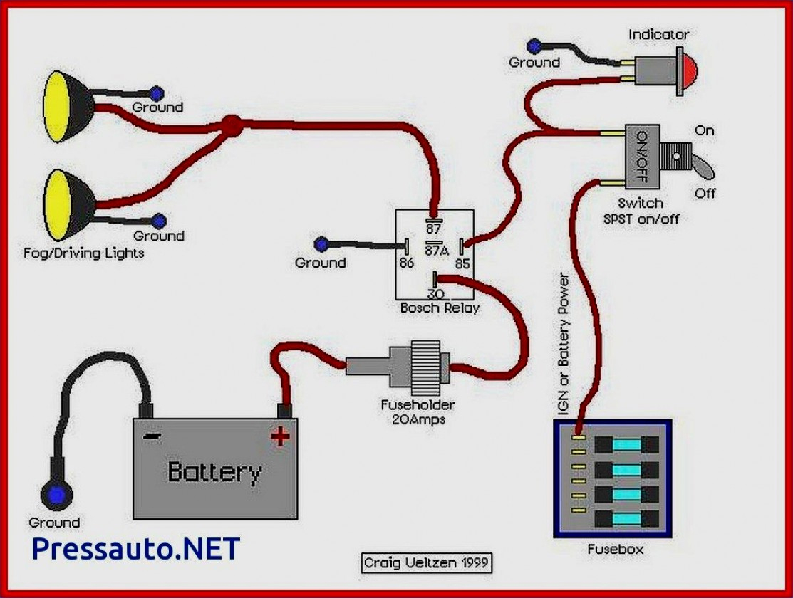
A relay diagram for fog lights provides the essential electrical roadmap required to install, modify, or repair auxiliary forward-illumination systems on a motor vehicle. Operating auxiliary lamps directly through a factory dashboard switch creates extreme thermal stress on internal contacts due to high current draw. Integrating a dedicated electromechanical switching device protects the cockpit wiring harness by routing heavy operating current directly from the battery through a separate fused circuit. Mastering these schematics prevents melted switches, erratic lighting performance, and unexpected electrical fires in 12-volt and 24-volt automotive applications. Technicians and DIY builders rely on these technical layouts to verify pin configurations, trace continuity, and ensure every connection complies with industry standards governed by organizations like the Society of Automotive Engineers (SAE). Comprehensive insights into these configurations are available within Vehicle Wiring Diagrams.
💡 Technical Key Takeaways:
- Core Focus: Diagnostic schematic and terminal connection layout for Relay Diagram For Fog Lights.
- Target Scope: Field technicians, automotive DIYers, and residential/commercial electricians.
- Safety Rule: Always disconnect the primary power source/battery terminal and verify zero voltage with a multimeter before touching wires.
Core Concepts and Wiring Fundamentals
An automotive relay functions as an electrically operated remote switch containing two distinct circuits: a low-power control circuit and a high-power load circuit. The control circuit utilizes thin-gauge wire to carry minimal current from the ignition or headlamp switch to energize an internal electromagnetic coil. When voltage is applied across the coil terminals, a magnetic field pulls a movable armature closed, completing the load circuit. This heavy-duty load circuit pulls power through thicker copper conductors directly from the power source, passing through a protective fuse before feeding the lighting loads.
Fuses serve as the primary line of defense against overcurrent conditions, melting their internal metallic links to interrupt power if a short circuit develops in the harness. Vehicle power sources typically originate at the positive battery terminal or the main under-hood power distribution center. Grounding is equally critical; a secure chassis ground ensures the completed return path has minimal resistance, preventing voltage drop that dims the output of halogen or LED lamps. Regional wiring practices dictate specific conductor color codes, varying between North American standards and British Standard BS 7671 conventions in the UK, making verification with a digital multimeter essential before making permanent connections.
[Finding] — According to the National Fire Protection Association (NFPA), electrical failures and malfunctions remain a leading factor in vehicle fires, highlighting the necessity of proper fusing and relay sizing.
Diagram Explanation and Key Components
Reading a relay diagram for fog lights requires familiarity with ISO standard numbering conventions assigned to automotive switching terminals. Pin 30 represents the fused constant power feed coming directly from the battery positive terminal. Pin 87 acts as the normally open output contact that routes high current out to the positive leads of the fog lamps when the coil is energized. Pin 85 serves as the negative ground feed or trigger input for the control coil, while Pin 86 receives the switched positive signal from the cabin switch or high-beam trigger wire. Some multi-function relays include an additional Pin 87a, which represents a normally closed contact that remains unpowered until the coil is activated.
Schematics utilize standardized graphical symbols to represent fuses, resistors, diodes, and incandescent or solid-state loads. Line types distinguish between high-current power paths and low-current signal wires, often utilizing thicker traces for load circuits. Understanding how these symbols interconnect prevents crossed wires during custom installations. Further details on deciphering these schematics are outlined in Wiring Diagram Basics.
Common Problems and Troubleshooting Methods
Systematic fault-finding begins by verifying whether the issue stems from the low-current control side or the high-current load side of the circuit. Common failures include blown fuses, corroded relay sockets, loose chassis grounds, and internally burned relay contacts caused by excessive vibrational wear or moisture intrusion. When auxiliary lamps fail to illuminate, diagnostic testing should follow a logical sequence using a digital multimeter or a fused test light.
Begin by checking the inline or distribution box fuse for continuity. Next, test for battery voltage at Pin 30 of the relay socket with the circuit active. Actuate the cabin switch while listening for an audible click inside the housing, which confirms the internal coil is energizing. If the coil clicks but power fails to pass through to Pin 87, the internal contacts have failed, requiring component replacement. If the coil does not energize, check the control side for voltage at Pin 86 and continuity to ground at Pin 85. For deeper analysis of electrical faults, consult Wiring Troubleshooting.
Practical Tips and Safety Considerations
Before performing any electrical modifications or diagnostic procedures on a vehicle, disconnect the negative battery terminal to prevent accidental short circuits, component damage, or personal injury from high current spikes. Select wire gauges appropriate for the maximum current draw of the lighting system; undersized conductors generate hazardous heat and cause noticeable voltage drop at the bulb sockets. Secure all wiring harnesses away from moving steering components, sharp metal edges, and high-temperature exhaust headers using flame-retardant loom and insulated P-clamps.
Weatherproofing connections is vital for exterior lighting exposed to road salt, water spray, and thermal cycling. Utilize heat-shrinkable butt connectors with integrated adhesive linings or properly crimped and soldered terminals sealed with marine-grade heat shrink. Avoid running high-current accessory circuits through factory lighting control modules without verifying maximum allowable amperage ratings specified by the vehicle manufacturer.
Conclusion
Utilizing a proper relay diagram for fog lights ensures safe, reliable operation by isolating sensitive dashboard switches from heavy electrical loads. Correctly identifying terminal pins, sizing fuses appropriately, and maintaining secure ground paths eliminate common points of failure in auxiliary lighting installations. Meticulous adherence to electrical safety protocols and systematic diagnostic procedures guarantees long-term system integrity. Reviewing specialized configurations in Relay and Component Wiring Diagrams provides additional knowledge for managing complex automotive electrical modifications.
Quick Wiring Specifications & Terminal Guide
| Component / Circuit | Standard Wire Gauge | Recommended Protection |
|---|---|---|
| Control & Trigger Signals | 18 – 20 AWG | 5A – 7.5A Inline Fuse |
| Standard Auxiliary Load | 14 – 16 AWG | 15A – 20A Circuit Breaker |
| Main Power Feed / Supply | 10 – 12 AWG | 30A – 40A Heavy-Duty Relay |
Images References