Introduction
A prestolite marine alternator wiring diagram serves as the definitive technical blueprint for understanding how heavy-duty charging systems interface with marine inboard or outboard engines. These diagrams matter because marine electrical infrastructure operates in an aggressive, highly corrosive environment where wiring failures escalate quickly into severe safety hazards. This documentation is relied upon heavily within the commercial marine sector, recreational boating, and mobile generator sets running 12-volt or 24-volt direct current (DC) architectures. Mastering these schematics improves troubleshooting accuracy, ensures proper battery charging capacity, and prevents catastrophic electrical fires on the water.
💡 Technical Key Takeaways:
- Core Focus: Diagnostic schematic and terminal connection layout for Prestolite Marine Alternator Wiring Diagram.
- Target Scope: Field technicians, automotive DIYers, and residential/commercial electricians.
- Safety Rule: Always disconnect the primary power source/battery terminal and verify zero voltage with a multimeter before touching wires.
Core Concepts and Wiring Fundamentals
Marine charging systems rely on a closed-loop DC circuit designed to convert mechanical engine rotation into electrical energy capable of replenishing deep-cycle house banks and engine-start batteries. The fundamental architecture involves three primary pathways: the main high-amperage output conductor, the field excitation circuit, and the sensing or indicator circuit. Unlike automotive applications, marine engines incorporate spark-ignited or compression-ignited plants housed in confined engine compartments, requiring ignition-protected components that prevent stray electrical sparks from igniting fuel vapors.
Heavy-gauge copper conductors transport the rectified direct current from the alternator output stud, commonly labeled as the BAT terminal, directly to the battery switch or starter solenoid. Intermediate protection comes in the form of high-current marine-rated fuses or circuit breakers sized precisely to match the maximum output capacity of the generator. Grounding integrity remains paramount across salt-water environments; relying solely on the engine block is often insufficient, necessitating dedicated negative return cables routed back to a central negative bus bar to eliminate galvanic corrosion and voltage drop.
Control circuits utilize smaller-gauge wiring to energize the internal or external voltage regulator. The ignition switch supplies power to the excitation circuit, waking up the magnetic field inside the rotor assembly to initiate charging. Modern setups often integrate auxiliary terminals for tachometers or excitation lamps, requiring precise terminal identification to prevent internal diode damage. Technicians frequently consult Vehicle Wiring Diagrams and specialized marine references when adapting heavy-duty alternators to custom engine bays.
Electrical safety statistics indicate that vessel DC system failures and unmaintained high-current charging connections account for a significant percentage of onboard marine fires annually. — American Boat and Yacht Council (ABYC)
Diagram Explanation and Key Components
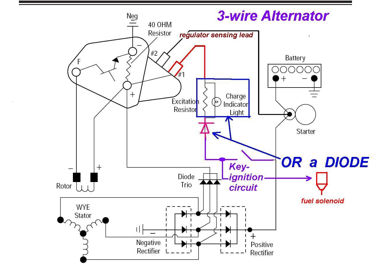
Reading a prestolite marine alternator wiring diagram requires familiarity with standardized symbolic representations for diodes, resistors, windings, and multi-pin connectors. The schematic outlines the alternator housing, internal rectifier bridge, regulator, and external connection posts. Standard terminal markings typically include “BAT” for battery output, “FLD” or “F” for the field winding, “AUX” or “R” for the stator tap, and “NEG” or “GRD” for ground. Some units feature an isolated ground stud, meaning the negative side of the charging circuit does not connect to the engine block.
Color coding on marine schematics generally follows regional standards such as SAE J1128 in North America or ISO 10133 for extra-low voltage DC installations. Red insulation designates positive unswitched high-amperage feeds, yellow or yellow-with-stripe designates DC negative returns, and brown or purple wires typically serve as ignition excitation or indicator light feeds. Technicians must always verify color allocations against the physical harness, as aftermarket modifications or previous repairs frequently introduce non-standard wire colors.
Decoding the schematic also involves identifying whether the alternator employs an internal solid-state regulator or relies on an advanced multi-stage external regulator. External regulating configurations add complexity, requiring direct voltage sense leads connected directly to the battery positive post to compensate for voltage drop across long cable runs. For broader context on how control devices interface within electrical networks, reviewing Relay and Component Wiring Diagrams provides valuable insight into switching high-current loads safely.
Common Problems and Troubleshooting Methods
Systematic diagnostic procedures for charging faults begin with a thorough visual inspection of all terminal connections, looking for the telltale green powdery buildup of copper chloride caused by marine moisture. Typical failures include open-circuit field wires, oxidized battery output studs, fatigued ground returns, and failed internal diodes within the rectifier bridge. Technicians approach these faults using a structured, step-by-step diagnostic process rather than relying on guesswork.
Initial testing involves measuring resting battery voltage with a digital multimeter, followed by checking system voltage while the engine runs at fast idle. A healthy charging system should register between 13.8 and 14.4 volts on a 12-volt system. If voltage remains static at battery resting levels, the technician disconnects the negative battery cable before inspecting continuity on the excitation wire and verifying that the ignition switch supplies proper voltage to the regulator wake-up terminal.
Voltage drop testing across the main positive cable and negative return path isolates high-resistance connections under heavy electrical loads. Any reading exceeding fractional voltage limits indicates excessive resistance caused by a loose crimp, internal wire strand corrosion, or undersized conductors. When tracking down intermittent faults or complex harness routing throughout auxiliary systems, referencing structured resources like Wiring Troubleshooting guides helps streamline fault isolation.
Practical Tips and Safety Considerations
High-current marine electrical work demands strict adherence to safety protocols, starting with disconnecting the battery negative terminal before servicing any alternator connections to prevent accidental arcing or tool welding. Marine installations must utilize stranded, tinned-copper wire compliant with UL 1426 standards to resist moisture wick-back and internal corrosion. Standard automotive untinned copper wire degrades rapidly in marine bilge environments, leading to hidden high-resistance faults.
Proper wire sizing is critical; undersized conductors subjected to continuous high-amperage output will overheat, degrade insulation, and pose a severe fire hazard. Terminal lugs must be applied using calibrated ratchet crimpers rather than standard pliers, followed by the application of adhesive-lined heat shrink tubing to seal the connection completely from salt air. Technicians should also ensure all belt-driven systems maintain correct pulley alignment and proper belt tension to prevent premature bearing wear and slip.
Adhering to guidelines established by organizations such as the American Boat and Yacht Council (ABYC) ensures compliance with recognized safety standards for marine electrical construction. Where local regulations mandate certified professional installation, or when dealing with complex multi-bank charging systems, consulting a qualified marine electrician is strongly advised to verify system integrity.
Conclusion
Interpreting a prestolite marine alternator wiring diagram bridges the gap between mechanical engine maintenance and reliable onboard electrical performance. Recognizing terminal designations, understanding correct wire sizing, and executing systematic diagnostic checks protect marine vessels against unexpected electrical failures at sea. Proper installation practices, combined with diligent maintenance of high-current connections, ensure long-term charging efficiency and operational safety across all aquatic environments. For further exploration of supporting electrical systems, review Wiring Diagram Basics to strengthen schematic interpretation skills.
Quick Wiring Specifications & Terminal Guide
| Component / Circuit | Standard Wire Gauge | Recommended Protection |
|---|---|---|
| Control & Trigger Signals | 18 – 20 AWG | 5A – 7.5A Inline Fuse |
| Standard Auxiliary Load | 14 – 16 AWG | 15A – 20A Circuit Breaker |
| Main Power Feed / Supply | 10 – 12 AWG | 30A – 40A Heavy-Duty Relay |
Images References