Introduction
Learning how to wire remote to dump trailer control boxes involves establishing a reliable electrical link between a hand-held pendant or wireless receiver and the hydraulic power unit. This process matters because heavy-duty hydraulic pumps demand significant electrical current, requiring robust switching components to prevent thermal overload and catastrophic system failure. Dump trailers are widely used in commercial construction, agriculture, and landscaping across North America, the United Kingdom, Australia, and various international markets. Understanding proper wiring methodology ensures the lift mechanism operates predictably, minimizes voltage drop over long cable runs, and prevents accidental hydraulic engagement that can endanger operators and bystanders.
💡 Technical Key Takeaways:
- Core Focus: Diagnostic schematic and terminal connection layout for How To Wire Remote To Dump Trailer.
- Target Scope: Field technicians, automotive DIYers, and residential/commercial electricians.
- Safety Rule: Always disconnect the primary power source/battery terminal and verify zero voltage with a multimeter before touching wires.
Core Concepts and Wiring Fundamentals
Dump trailer remote wiring relies on a 12-volt or 24-volt direct current (DC) automotive architecture supplied by a dedicated deep-cycle auxiliary battery mounted on the trailer tongue. High-current electromechanical solenoids, often called contactors, bridge the gap between the battery and the reversible electric motor driving the hydraulic pump. A solenoid is a magnetically operated switch that uses a low-current control signal from the remote handset to close a heavy-duty internal contact, routing high amperage safely to the motor windings. Fuses or manual reset circuit breakers protect the main feeder line against short circuits, acting as sacrificial safety devices that interrupt power before wiring harnesses melt.
Control circuits handle minimal electrical load, transmitting simple switched signals back to the solenoid coils for raising and lowering functions. Power distribution blocks and weather-resistant junction boxes keep connections free from moisture, road salt, and debris. Ground integrity remains paramount; hydraulic pumps bolted directly to painted trailer frames often suffer from high resistance unless a dedicated negative return cable links the pump housing directly back to the battery negative terminal. Ignoring this principle introduces intermittent electrical faults that frustrate even experienced technicians during field service.
[Vehicle and trailer electrical failures frequently stem from inadequate chassis grounding rather than component defects, highlighting the necessity of clean, direct negative return paths.] — [Society of Automotive Engineers (SAE) Technical Guidelines]
Diagram Explanation and Key Components
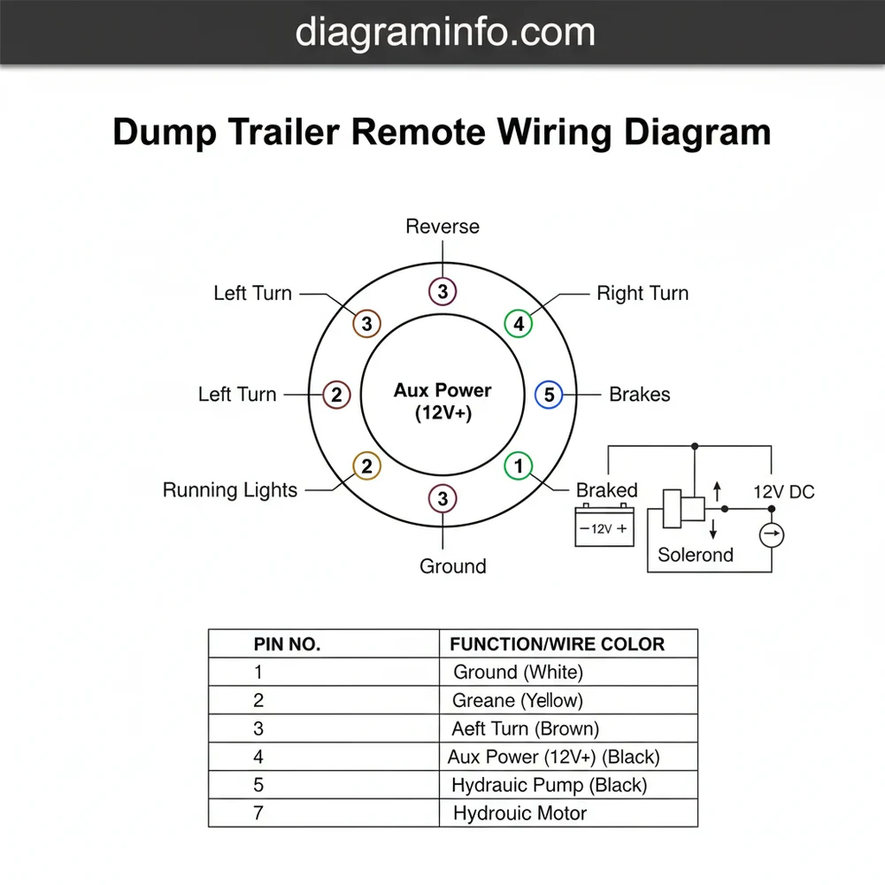
Reading schematic diagrams for how to wire remote to dump trailer setups requires familiarity with standard automotive electrical symbols, including battery icons, switch contacts, coil windings, and chassis ground symbols. Standard wiring diagrams typically illustrate the hand-held pendant with a multi-conductor cable containing wires for constant power, raise control, and lower control. Color codes vary extensively between manufacturing regions and aftermarket brands; for instance, standard North American aftermarket kits frequently utilize a red wire for battery positive, a blue wire for raise, and a yellow or black wire for lower, whereas European and Australian assemblies often apply different numeric or color-coded tracing standards.
Detailed schematics can be cross-referenced with Vehicle Wiring Diagrams to understand how trailer plugs interface with tow vehicle auxiliary charging lines. The hand pendant or wireless receiver module acts as the central command node, routing incoming 12V power through internal momentary switches to the corresponding solenoid trigger terminals. Technicians must trace each line carefully from the pendant plug, through the rubber grommet in the hydraulic enclosure, to the threaded studs on the dual-solenoid valve block.
Common Problems and Troubleshooting Methods
Diagnosing faults in a dump trailer remote circuit involves a systematic, step-by-step verification process utilizing a digital multimeter to isolate voltage drops and open circuits. Typical failure symptoms include a clicking solenoid that fails to engage the motor, total electrical silence when pressing the remote buttons, or a motor that runs continuously without user input due to a welded solenoid contact. Technicians should approach troubleshooting by first verifying source battery voltage under load, then checking the condition of inline fuses and fusible links.
If the motor fails to turn while the solenoid clicks audibly, the fault usually lies in excessive resistance across the main power cables or burned contact points inside the heavy-duty relay. Reference materials found in Wiring Troubleshooting provide structured fault-finding trees for isolating such continuity breaks. Testing the control side requires probing the remote connector terminals while actuating the buttons to ensure 12V signal transmission reaches the solenoid trigger spade connectors. Always disconnect the main power feed before replacing heavy-duty contactors to prevent accidental arcing against the metal hydraulic reservoir.
Practical Tips and Safety Considerations
Executing professional installations requires adherence to established industry practices outlined by organizations such as the National Fire Protection Association (NFPA) in the US, the Canadian Standards Association (CSA) in Canada, or equivalent international bodies. High-current motor leads must feature heavy-gauge copper wiring—typically 4 AWG or 2 AWG—to prevent dangerous overheating and severe voltage drop during heavy lifting cycles. Technicians must secure all wiring harnesses with rubber-coated P-clamps and protective loom to prevent chafing against sharp steel frame edges during transit.
Before initiating any electrical work, disconnect the trailer breakaway system and isolate the battery by removing the negative terminal clamp. Safety props must be physically locked under the raised dump box prior to performing any maintenance beneath the bed, guarding against catastrophic hydraulic collapse. Welders and grinders used during custom bracket fabrication must never use the trailer wiring harness as a ground return path, as high-frequency electrical currents can fry solid-state wireless remote receivers.
Conclusion
Mastering how to wire remote to dump trailer systems elevates both operational reliability and workplace safety across mobile hydraulic applications. Proper component selection, meticulous circuit protection, and secure grounding practices ensure years of trouble-free lifting performance under demanding field conditions. For further guidance on auxiliary electrical systems, consult specialized documentation including Relay and Component Wiring Diagrams to refine your diagnostic and installation expertise.
Quick Wiring Specifications & Terminal Guide
| Component / Circuit | Standard Wire Gauge | Recommended Protection |
|---|---|---|
| Control & Trigger Signals | 18 – 20 AWG | 5A – 7.5A Inline Fuse |
| Standard Auxiliary Load | 14 – 16 AWG | 15A – 20A Circuit Breaker |
| Main Power Feed / Supply | 10 – 12 AWG | 30A – 40A Heavy-Duty Relay |
Images References