Introduction
Karavan boat trailer wiring is the specialized 12-volt direct current (DC) electrical network designed to transmit lighting, braking, and auxiliary power signals from a towing vehicle to a watercraft transport trailer. This wiring architecture is essential for road safety, ensuring that running lights, brake lights, and turn signals remain fully visible to surrounding traffic during transit. Watercraft trailers face harsh operational environments involving regular immersion in freshwater or saltwater, vibration, and thermal cycling. Understanding this system improves installation quality, prevents lighting failures, and reduces the risk of roadside citations or collisions. For additional context on how mobile electrical networks function, consult Vehicle Wiring Diagrams.
💡 Technical Key Takeaways:
- Core Focus: Diagnostic schematic and terminal connection layout for Karavan Boat Trailer Wiring.
- Target Scope: Field technicians, automotive DIYers, and residential/commercial electricians.
- Safety Rule: Always disconnect the primary power source/battery terminal and verify zero voltage with a multimeter before touching wires.
Core Concepts and Wiring Fundamentals
The karavan boat trailer wiring system operates on a standard 12V DC architecture supplied by the tow vehicle’s battery and alternator. Power distribution relies on multi-strand copper cables bundled inside protective PVC or braided jackets to withstand constant flexing. Ground paths complete the electrical circuit; while many older trailers rely solely on the steel trailer frame and hitch ball for continuity, modern marine wiring practice strongly advocates for dedicated white ground wires running directly from each lamp housing back to the main harness connector. Voltage drops, corrosion, and high resistance are the primary enemies of these low-voltage circuits.
Connectors and splices represent the most vulnerable points in any trailer harness due to capillary action drawing moisture into the copper strands. Waterproof heat-shrink butt connectors containing adhesive lining are standard for sealing joints against environmental intrusion. Fuses protecting these circuits are typically housed in the tow vehicle’s interior or under-hood fuse panel, sized according to the total current draw of the trailer lighting array. For those exploring more intricate control systems, reviewing Relay and Component Wiring Diagrams provides valuable insight into heavy-duty circuit protection.
Trailer Lighting Failures — According to National Highway Traffic Safety Administration (NHTSA) vehicle safety reports, lighting and signaling defects remain among the most frequent citations issued during roadside commercial and recreational trailer inspections.
Diagram Explanation and Key Components
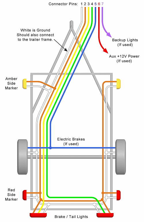
Reading a schematic for karavan boat trailer wiring requires familiarity with standardized automotive wire color codes and plug configurations, such as the flat 4-way or round 7-way blade connectors defined by the Society of Automotive Engineers (SAE). In a standard 4-way flat plug, the white wire designates the system ground, the brown wire controls the running, tail, and clearance lights, the yellow wire operates the left turn signal and stop lamps, and the green wire manages the right turn signal and stop lamps. Trailers equipped with hydraulic surge brakes or electric drum brakes utilize additional circuits, typically blue for electric brake activation and black or purple for auxiliary 12V power or reverse lockout solenoids.
Schematics utilize standardized line types and symbols to represent splices, ground points, fuses, and lamp filaments. Solid lines indicate active power-carrying conductors, while dashed lines often represent mechanical linkage or secondary chassis grounds. Interpreting these diagrams accurately requires matching the vehicle-side pinout to the trailer-side harness, noting that international standards or aftermarket adapters may occasionally vary wire colors, necessitating physical meter verification before final connection. To master the foundational rules of reading these schematics, refer to Wiring Diagram Basics.
Common Problems and Troubleshooting Methods
Systematic diagnostic procedures for karavan boat trailer wiring begin with isolating the fault to either the tow vehicle or the trailer itself using a digital multimeter or a 12V circuit tester. Typical failures include intermittent ground faults caused by rust on the frame, blown fuses in the tow vehicle due to pinched wires, and oxidized lamp sockets resulting in dimmed or non-functioning bulbs. Technicians should first verify that the tow vehicle’s socket delivers proper voltage across the running, stop, and turn terminals when activated, eliminating the vehicle as the source of failure before inspecting the trailer harness.
When troubleshooting trailer-side issues, the diagnostic process follows the signal path backward from the non-working lamp to the main harness plug. Continuity testing on the ground wire is critical, as a corroded frame mounting point will cause feedback loops, dimming multiple bulbs simultaneously whenever the brakes or turn signals are applied. Cleaning terminal surfaces to bare metal, applying dielectric grease, and replacing damaged sections of wire with marine-grade tinned copper resolves the majority of connectivity faults. For further guidance on isolating complex electrical faults, consult Wiring Troubleshooting.
Practical Tips and Safety Considerations
Best practices for installing and maintaining karavan boat trailer wiring involve using tinned copper wire, which resists oxidation far better than standard bare copper when exposed to moisture. All wire runs must be secured to the trailer frame every 12 to 18 inches using UV-resistant zip ties or stainless steel P-clamps to prevent chafing against sharp metal edges. Avoid using scotch-lock insulation-displacement connectors, as these trap water and accelerate internal conductor corrosion. Always disconnect the tow vehicle’s negative battery terminal or unplug the trailer harness before performing any cutting, splicing, or rewiring work to prevent accidental short circuits.
Conclusion
Proper installation and meticulous maintenance of karavan boat trailer wiring ensure reliable signaling, legal compliance, and safe transport of watercraft across varying road and weather conditions. By prioritizing waterproof connections, robust grounding strategies, and systematic diagnostic workflows, technicians and DIY enthusiasts can eliminate common electrical failures. Diligent adherence to manufacturer specifications and recognized automotive standards guarantees long-term durability for every marine towing application.
Quick Wiring Specifications & Terminal Guide
| Component / Circuit | Standard Wire Gauge | Recommended Protection |
|---|---|---|
| Control & Trigger Signals | 18 – 20 AWG | 5A – 7.5A Inline Fuse |
| Standard Auxiliary Load | 14 – 16 AWG | 15A – 20A Circuit Breaker |
| Main Power Feed / Supply | 10 – 12 AWG | 30A – 40A Heavy-Duty Relay |
Images References