Introduction
Mastering 1981 evinrude ignition switch wiring is essential for anyone restoring vintage outboards or maintaining marine 12V DC systems. This specific vintage marine harness interfaces the dash-mounted key switch with the power pack, starter solenoid, choke, and safety lanyard. Outboard electrical systems operate in harsh, moisture-rich environments prone to salt corrosion and vibration fatigue. Understanding how these circuits interconnect improves diagnostic accuracy and prevents costly component damage. Mechanics and DIY enthusiasts working on marine engines often reference Vehicle Wiring Diagrams to understand parallel DC switching layouts, though marine setups feature unique ignition grounding loops.
💡 Technical Key Takeaways:
- Core Focus: Diagnostic schematic and terminal connection layout for 1981 Evinrude Ignition Switch Wiring.
- Target Scope: Field technicians, automotive DIYers, and residential/commercial electricians.
- Safety Rule: Always disconnect the primary power source/battery terminal and verify zero voltage with a multimeter before touching wires.
Core Concepts and Wiring Fundamentals
Marine ignition switches function as multi-pole rotary switches that route 12-volt direct current from the battery and starter solenoid to various engine management circuits. The typical vintage outboard setup utilizes a push-to-choke design where turning the key to the run position closes the main circuit, while pushing the key inward activates the electric primer solenoid. Power flows through specific pin designations labeled Battery (B), Ignition (I), Solenoid (S), Choke (C), and Magneto (M). The Magneto circuit plays a critical role because it kills the engine by grounding the ignition power pack when the key is turned to the off position. This operational design is the exact inverse of standard automotive ignition setups, which require applied voltage to run.
Corrosion inside the dash binnacle frequently creates high-resistance connections, leading to voltage drop at the starter solenoid coil. Technicians must inspect terminal eyelets, rubber boot seals, and plug-in harness connectors for green powdery oxidation, which signals internal copper degradation. In accordance with guidelines from the American Boat and Yacht Council (ABYC), marine electrical systems require stranded tinned-copper wire to resist galvanic corrosion in saltwater environments. Whenever replacing sections of the harness, matching the correct American Wire Gauge (AWG) size prevents excessive voltage loss over long hull runs.
[Finding] — According to the American Boat and Yacht Council (ABYC), environmental corrosion is a leading contributor to marine electrical resistance failures and subsequent component overheating.
Diagram Explanation and Key Components
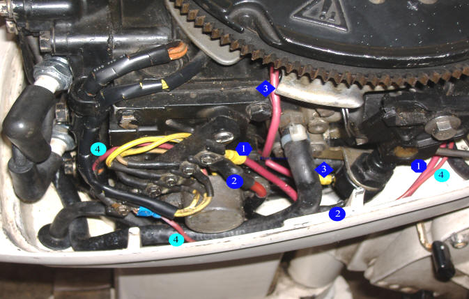
Reading technical diagrams for 1981 evinrude ignition switch wiring requires familiarity with standardized marine color coding established by industry groups like the Society of Automotive Engineers (SAE). On standard OMC (Omnibus Marine Corporation) harnesses, the red wire delivers unswitched positive battery power, the purple wire feeds switched 12V ignition power to gauges and the power pack, and the black/yellow stripe wire controls the emergency stop and ignition kill circuit. The black wire handles the system ground, while the white wire activates the electric choke solenoid. Interpreting these schematic lines accurately prevents cross-wiring the kill circuit with battery power, which can permanently ruin solid-state ignition components.
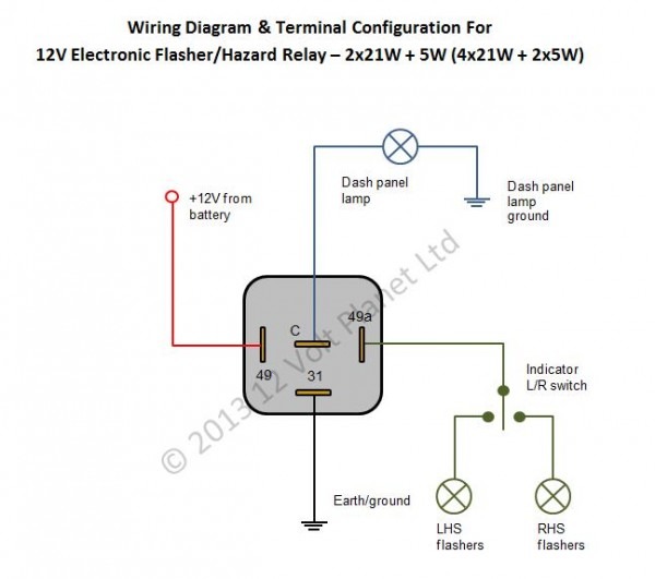
The ignition switch housing itself contains mechanical spring-loaded contacts that wear out over decades of exposure to coastal humidity. When troubleshooting multi-pin plug connectors, technicians frequently utilize Relay and Component Wiring Diagrams to trace auxiliary circuits like tilt-trim motors or safety lanyards that tie into the main dash harness. Recognizing standard schematic symbols—such as single-pole single-throw switches, open contacts, and chassis ground symbols—simplifies the process of isolating a faulty switch from a failing power pack.
Common Problems and Troubleshooting Methods
Systematic fault-finding begins by verifying battery state of charge and checking the main inline fuse located near the starter solenoid. If the starter motor fails to engage when the key turns to the start position, a technician must measure voltage drop across the starter switch terminal using a digital multimeter set to DC volts. An open circuit in the black/yellow kill wire will prevent the motor from starting or, conversely, prevent the engine from shutting off when the key turns to the off position. Mechanics should isolate the harness at the engine plug and test continuity through each wire strand to rule out internal breaks caused by constant steering cable movement.
Intermittent stalling often points to an intermittent ground path within the emergency stop switch or a failing ignition switch faceplate. Diagnosing these complex electrical faults safely requires structured methodologies outlined in proper Wiring Troubleshooting guides, ensuring that live voltage tests do not create accidental short circuits against aluminum engine blocks.
Practical Tips and Safety Considerations
Safety is paramount when servicing marine electrical systems due to the presence of fuel vapors in enclosed engine cowlings and high current capacities from marine batteries. Always disconnect the negative battery terminal before servicing dash switches or unbolting harness connections near the starter solenoid. Use marine-grade heat-shrink tubing containing adhesive lining to seal all crimped wire splices against moisture ingress. Avoid soldering marine wire runs in high-vibration areas, as solder wicks up the strands and creates a brittle pivot point prone to snapping under engine harmonics.
When mounting replacement ignition switches, apply a light coating of dielectric grease to the spade terminals to ward off future oxidation. Double-check all terminal torque specifications and ensure wire bundles are secured with UV-resistant nylon cable ties away from sharp fiberglass edges or moving steering linkages.
Conclusion
Properly diagnosing and repairing 1981 evinrude ignition switch wiring ensures reliable engine operation on the water and extends the lifespan of vintage marine electronics. By respecting factory color codes, utilizing corrosion-resistant components, and adhering to established ABYC guidelines, technicians and hobbyists can achieve professional-grade electrical results. Methodical testing paired with careful attention to mechanical connections remains the cornerstone of successful marine electrical restoration. For further guidance on designing and repairing auxiliary systems, explore additional resources on Wiring Diagram Basics.
Quick Wiring Specifications & Terminal Guide
| Component / Circuit | Standard Wire Gauge | Recommended Protection |
|---|---|---|
| Control & Trigger Signals | 18 – 20 AWG | 5A – 7.5A Inline Fuse |
| Standard Auxiliary Load | 14 – 16 AWG | 15A – 20A Circuit Breaker |
| Main Power Feed / Supply | 10 – 12 AWG | 30A – 40A Heavy-Duty Relay |
Images References