Introduction
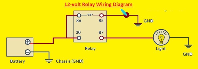
A diagram showing how to wire a 12v relay serves as the essential blueprint for managing high-current electrical loads using low-current control switches. This component appears frequently in automotive upgrades, marine electrical systems, off-grid solar setups, and industrial control panels. A relay acts as an electromagnetic switch, protecting delicate dashboard switches, electronic control units, and thin wiring harnesses from thermal overload. Master technicians rely on these schematics to ensure that accessories like auxiliary driving lights, electric cooling fans, and high-output fuel pumps receive uninterrupted battery voltage without voltage drop. Understanding how to interpret and execute these wiring configurations improves installation quality, prevents catastrophic electrical fires, and dramatically reduces diagnostic time when electrical faults occur.
💡 Technical Key Takeaways:
- Core Focus: Diagnostic schematic and terminal connection layout for A Diagram Showing How To Wire A 12V Relay.
- Target Scope: Field technicians, automotive DIYers, and residential/commercial electricians.
- Safety Rule: Always disconnect the primary power source/battery terminal and verify zero voltage with a multimeter before touching wires.
Core Concepts and Wiring Fundamentals
A standard automotive-style 12-volt relay utilizes two separate circuits: a low-power control circuit and a high-power load circuit. The control circuit consists of a switch, a power source, and the relay coil, which creates an electromagnetic field when energized. This magnetic field pulls a movable armature closed, completing the load circuit that connects the battery directly to the target device. Fuses must always be incorporated into the high-amperage feed line as close to the power source as possible to protect against short circuits. Choosing the correct wire gauge is critical, as undersized conductors generate excessive heat and voltage drop under heavy electrical loads.
Regional standards dictate wire color conventions and installation practices across different jurisdictions. In North America, the SAE (Society of Automotive Engineers) guidelines apply, whereas installations in the UK, Australia, and Europe often follow distinct color-coding traditions and standards such as BS 7671 or AS/NZS 3000 for relevant low-voltage applications. Technicians must always verify local codes and manufacturer specifications before cutting or terminating conductors. When working on DC electrical systems involving high-current accessories, safety protocols require disconnecting the battery negative terminal before starting any physical wiring modifications to prevent accidental arcing or component damage.
[Vehicle Electrical Fires] — According to National Fire Protection Association (NFPA) data, electrical failures and malfunctions rank among the leading causes of vehicle fires, emphasizing the necessity of proper fusing and relay integration.
Diagram Explanation and Key Components
Standard Bosch-style ISO relays feature a specific numbering convention stamped onto the housing underside to identify terminal functions. Terminal 30 represents the unswitched power feed coming directly from the battery or a fused power distribution block. Terminal 87 is the switched output that sends power out to the accessory or load when the relay is activated. Terminal 85 connects to the control switch or ground, while Terminal 86 completes the opposite side of the internal electromagnetic coil. Some specialized relays include a Terminal 87a, which provides normally closed power that disconnects when the coil energizes. Interpreting a schematic requires tracing both the control loop through terminals 85 and 86 and the power loop through terminals 30 and 87.
Wiring diagrams use standardized symbols to represent relay coils, normally open contacts, fuses, and grounds. A dashed line or different color coding typically separates the low-current control side from the heavy-gauge load side. Field experience shows that many installation errors stem from reversing terminals 85 and 86 on diodes-equipped relays, or mistaking terminal 87a for the primary output 87. Reviewing detailed resources found within Relay and Component Wiring Diagrams helps clarify these terminal designations and prevents costly miswirings.
Common Problems and Troubleshooting Methods
Systematic fault-finding begins with verifying that power is actually reaching the relay input terminals using a digital multimeter. A common real-world failure point is corrosion at the relay socket terminals due to moisture exposure in engine bays or under-chassis locations. If the control switch is activated but the relay fails to click, technicians must test for voltage at terminal 86 and continuity to ground at terminal 85. An open relay coil, a blown inline fuse, or a high-resistance ground connection will prevent the electromagnetic field from forming. Technicians also encounter thermal fatigue where cheap aftermarket relay sockets melt due to excessive current draw exceeding the contact rating.
Diagnostic procedures should follow a logical path from the power source to the load. First, check the main feed voltage at terminal 30. Second, verify control voltage and switch operation. Third, test the output at terminal 87 under a simulated load rather than an open circuit, because a multimeter can sometimes show 12 volts even if a corroded wire cannot pass actual operating current. For further guidance on diagnosing complex electrical networks, consult the articles available under Wiring Troubleshooting to refine diagnostic workflows.
Practical Tips and Safety Considerations
Professional installations demand proper mechanical protection, including split loom tubing, heat shrink tubing with adhesive lining, and secure zip-tying away from moving parts and exhaust components. Crimping connections with professional ratcheting tools ensures a gas-tight electrical connection that resists vibration failure. Avoid twisting wires together and wrapping them in electrical tape, as this method invites corrosion and high-resistance joints. Whenever modifying circuits that interface with sensitive vehicle computers or industrial controllers, double-check that the relay coil incorporates a flyback diode or resistor to suppress voltage spikes when the magnetic field collapses.
Safety remains paramount when handling high-current DC systems. Always de-energize the circuit, disconnect power supplies or battery terminals, and verify zero energy state with a calibrated multimeter before touching exposed terminals. Qualified technicians must perform installations where local regulations or manufacturer warranties require certified labor. For broader foundational knowledge regarding schematic symbols and layout rules, explore the reference materials categorized under Wiring Diagram Basics.
Conclusion
Mastering the layout and interpretation of relay schematics bridges the gap between basic electrical theory and professional installation execution. Proper adherence to terminal numbering, correct wire sizing, and robust fusing protects equipment from thermal damage and ensures long-term reliability. Systematic diagnostic methods save valuable time when tracking down intermittent electrical faults in complex machinery and vehicles. Applying these rigorous standards elevates the quality and safety of any electrical project, whether working on automotive upgrades, mobile electronics, or custom control panels.
Quick Wiring Specifications & Terminal Guide
| Component / Circuit | Standard Wire Gauge | Recommended Protection |
|---|---|---|
| Control & Trigger Signals | 18 – 20 AWG | 5A – 7.5A Inline Fuse |
| Standard Auxiliary Load | 14 – 16 AWG | 15A – 20A Circuit Breaker |
| Main Power Feed / Supply | 10 – 12 AWG | 30A – 40A Heavy-Duty Relay |
Images References





