Introduction
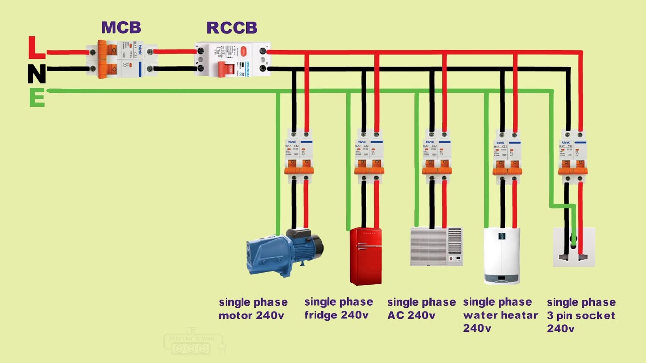
A 240 volt single phase wiring diagram for house installations illustrates the complete electrical pathway required to deliver high-capacity alternating current to heavy-duty residential loads such as central air conditioners, electric ranges, and water heaters. This system operates by utilizing two distinct hot conductors alongside a neutral and a protective earth wire, effectively doubling the voltage potential supplied to standard household outlets. Understanding this layout matters significantly for technicians, DIY enthusiasts, and builders because heavy-load circuits demand precise adherence to electrical codes and load calculations to prevent catastrophic failure. The configuration is widely applied across residential distribution panels to feed large appliances requiring dedicated branch circuits. Comprehending these layouts improves installation quality, ensures compliance with regional standards, and enhances diagnostic accuracy during electrical repairs, which can be explored further in resources dedicated to Home Electrical Wiring Diagrams.
💡 Technical Key Takeaways:
- Core Focus: Diagnostic schematic and terminal connection layout for 240 Volt Single Phase Wiring Diagram For House.
- Target Scope: Field technicians, automotive DIYers, and residential/commercial electricians.
- Safety Rule: Always disconnect the primary power source/battery terminal and verify zero voltage with a multimeter before touching wires.
Core Concepts and Wiring Fundamentals
A 240V single-phase residential electrical system relies on a center-tapped transformer supplying two 120V hot legs that are 180 degrees out of phase with each other. When combined at a dual-pole circuit breaker, these two hot conductors provide the required potential difference to drive high-wattage equipment safely and efficiently.
Conductor sizing and insulation types form the backbone of any safe installation, matching the ampacity rating of the overcurrent protection device to prevent overheating. Voltage drop, ambient temperature, and conduit fill capacity dictate the exact gauge of copper or aluminum wire required for a specific run. Unbalanced loads, loose terminal screws, and degraded insulation represent primary culprits behind resistance heating and subsequent thermal events.
Protection devices such as circuit breakers and fused disconnects interrupt current flow immediately during a short circuit or ground fault condition. Proper bonding and grounding establish a low-impedance path to earth, ensuring that stray current reliably trips protective devices rather than energizing exposed metallic enclosures.
Improper electrical installations and overloaded circuits account for a substantial percentage of residential electrical fires annually, highlighting the critical need for correct wiring practices. — National Fire Protection Association (NFPA)
Diagram Explanation and Key Components
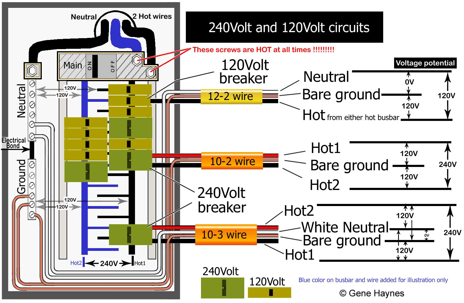
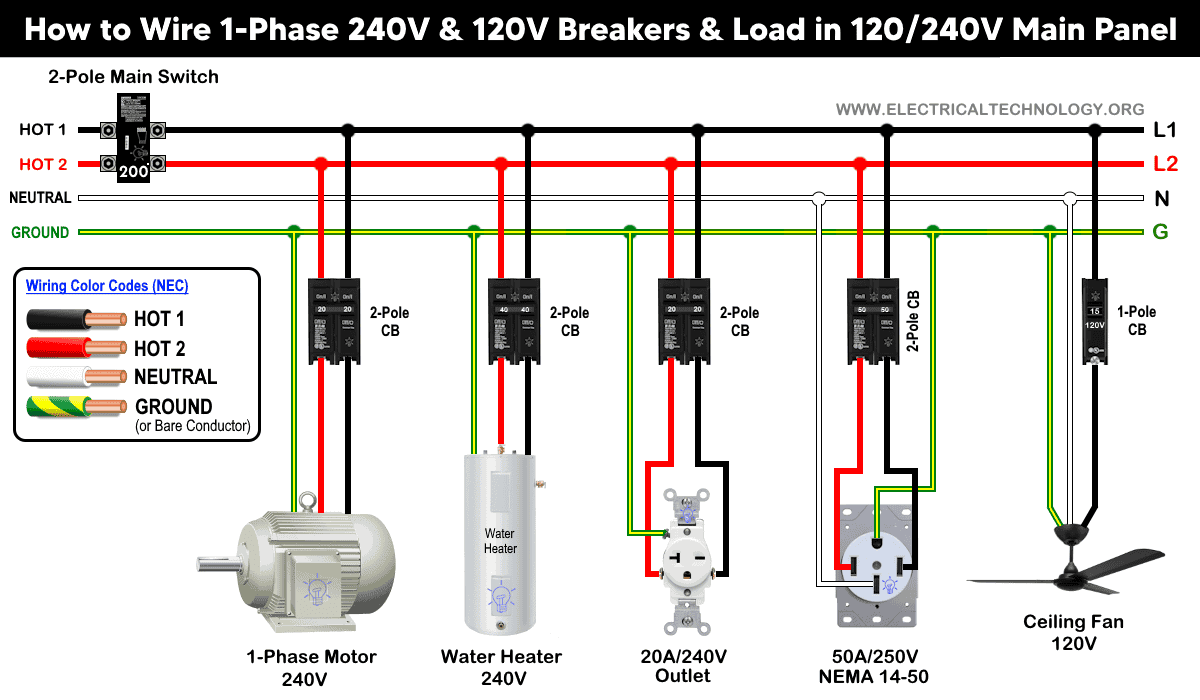
Reading a 240 volt single phase wiring diagram for house systems requires recognizing standardized electrical symbols representing circuit breakers, buses, terminals, and load appliances. Schematic lines denote conductors, with solid lines typically showing hot wires, while dashed or colored lines represent neutrals and bare or green wires denote equipment grounds. Colors vary significantly by region: North American installations under the National Electrical Code (NEC) or Canadian Electrical Code (CEC) generally utilize black and red for hot conductors, white or gray for neutral, and bare copper or green for ground. Conversely, systems governed by UK standards (BS 7671) or Australian standards (AS/NZS 3000) employ brown for phase, blue for neutral, and green-and-yellow for protective earth.
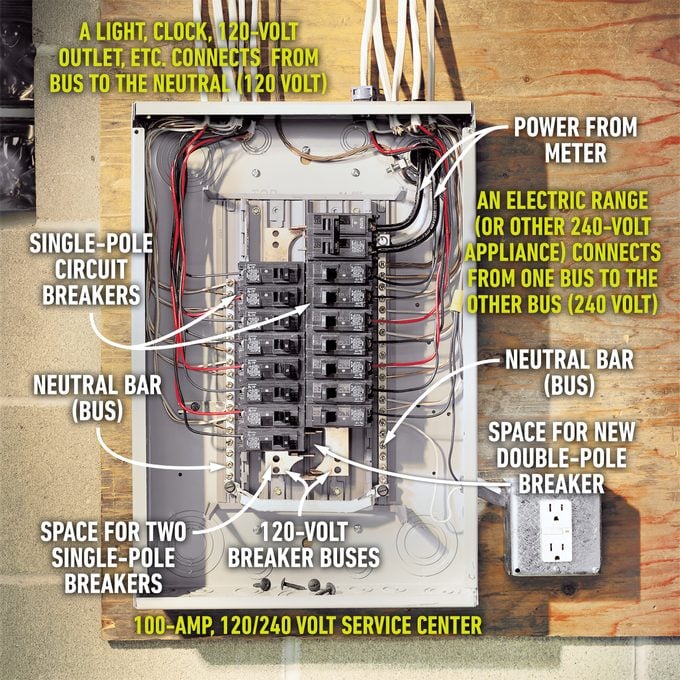
The circuit originates at the main service panel, where a double-pole breaker bridges two hot bus bars to supply 240 volts across the two ungrounded conductors. This wiring routes through appropriate cable assemblies or conduit to a junction box, safety switch, or directly to the appliance terminal block. Within heating units or motor loads, internal wiring diagrams govern how internal control relays, thermostats, and heating elements interface with the incoming supply voltage, principles often detailed in Appliance and Device Wiring.
Common Problems and Troubleshooting Methods
Systematic fault-finding for a 240V circuit involves methodical testing with a digital multimeter to isolate issues such as open-neutral conditions, dropped legs, or high-resistance terminal connections. Technicians begin by verifying voltage at the service panel, checking both individual hot-to-neutral measurements (approx. 120V each) and hot-to-hot measurements (approx. 240V) to ensure the dual-pole breaker is functioning correctly. A common real-world observation in older installations is thermal degradation at the breaker lugs due to cyclic expansion and contraction, which creates localized high resistance and intermittent power delivery.
When an appliance fails to heat or run despite a closed breaker, diagnostic procedures move downstream to local disconnects and terminal blocks. Technicians check for continuity across heating elements or motor windings while the circuit is completely de-energized, verifying that no internal short to ground exists. Loose wire nuts, corroded screw terminals, and pinched cables inside junction boxes frequently cause intermittent dropouts that mimic component failure. Safe troubleshooting always requires treating every conductor as live until proven otherwise with a verified meter, aligning with standard practices found in Wiring Troubleshooting.
Practical Tips and Safety Considerations
Mains-voltage electrical work demands strict adherence to safety protocols, starting with completely de-energizing the circuit at the main breaker panel and locking out the switch to prevent accidental re-engagement. Always verify zero energy state using a reliable voltage tester confirmed against a known live source before touching any exposed conductor or terminal. Personal protective equipment, insulated hand tools rated for electrical work, and dry working environments are mandatory safeguards against severe shock or arc flash injuries.
Code compliance dictates that wire sizing must never fall below the minimum ampacity required by the manufacturer and regional code bodies, such as the NEC in the United States or local equivalents elsewhere. Common amateur mistakes include failing to torque terminal screws to manufacturer specifications, omitting strain reliefs on cable entries, and mixing up neutral and ground paths in subpanels. Consulting local regulatory bodies or retaining a licensed electrician is necessary where regional law requires professional installation or permitting.
Conclusion
Mastering a 240 volt single phase wiring diagram for house projects requires careful attention to source voltages, conductor sizing, color coding conventions, and rigorous safety practices. Adhering to established standards set by authorities like NFPA or local electrical codes ensures that high-capacity circuits operate safely and reliably over their operational lifespan. Careful planning, systematic diagnostic testing, and respect for electrical hazards prevent equipment damage and personal injury. Further exploration of related schematics and foundational reading can be continued through guides on Wiring Diagram Basics.
Quick Wiring Specifications & Terminal Guide
| Component / Circuit | Standard Wire Gauge | Recommended Protection |
|---|---|---|
| Control & Trigger Signals | 18 – 20 AWG | 5A – 7.5A Inline Fuse |
| Standard Auxiliary Load | 14 – 16 AWG | 15A – 20A Circuit Breaker |
| Main Power Feed / Supply | 10 – 12 AWG | 30A – 40A Heavy-Duty Relay |
Images References