Introduction
A 5 pin relay diagram signal wire represents the core trigger path that commands an electromagnetic switch to transition power between two distinct circuits. Mastering this specific conductor prevents misdiagnoses in complex control loops and ensures heavy electrical loads receive steady power without overloading dash switches or electronic control units. These relays appear extensively in Vehicle Wiring Diagrams for managing high-draw accessories like auxiliary lighting, fuel pumps, and cooling fans. Understanding the signal wire on a single-pole double-throw relay clarifies how low-amperage triggers control high-amperage output, improving installation quality and minimizing electrical fires.
💡 Technical Key Takeaways:
- Core Focus: Diagnostic schematic and terminal connection layout for 5 Pin Relay Diagram Signal Wire.
- Target Scope: Field technicians, automotive DIYers, and residential/commercial electricians.
- Safety Rule: Always disconnect the primary power source/battery terminal and verify zero voltage with a multimeter before touching wires.
Core Concepts and Wiring Fundamentals
Electromechanical relays use a low-current control circuit to operate a high-current load circuit through a movable armature. A standard automotive or industrial ISO relay houses a coil and a set of internal switch contacts. Power feeds the main load, while a separate trigger line commands the internal electromagnet.
The signal wire acts as the low-amperage control command originating from a switch, sensor, or electronic module. When voltage or ground reaches this terminal, current flows through the internal coil, generating a magnetic field. This magnetic pull forces the internal switch to click over, changing the active output path.
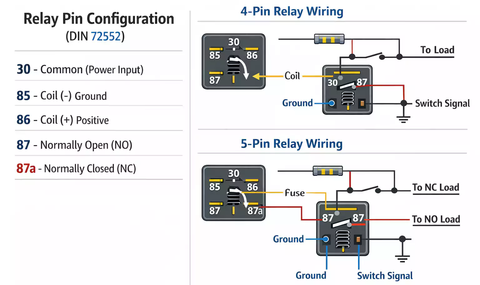
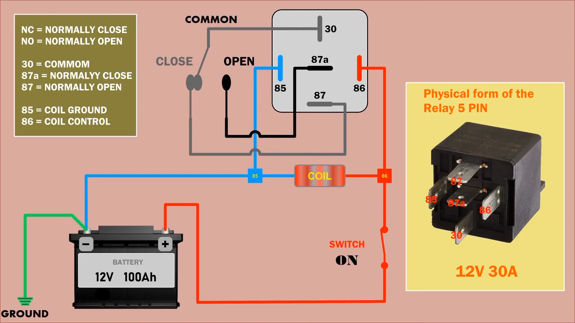
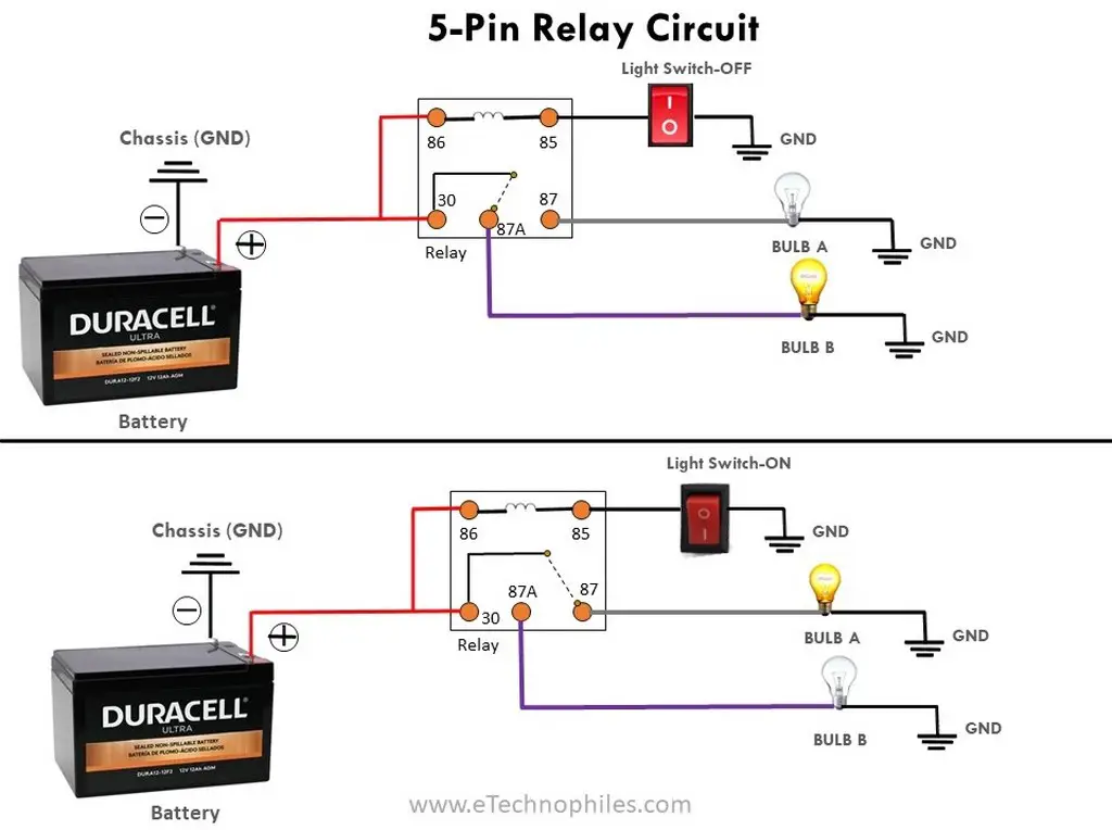
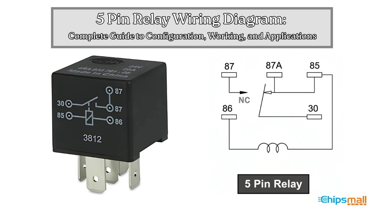
Understanding terminal identification standards simplifies installation across global jurisdictions. Automotive configurations typically follow ISO 7588 numbering, where terminals 85 and 86 form the control coil, terminal 30 supplies the incoming fused power, terminal 87 provides normally open output, and terminal 87a provides normally closed output. Wire color conventions vary by region and manufacturer, requiring technicians to rely on numbering rather than insulation hues.
[Automotive electrical failures frequently stem from moisture intrusion and corrosion at relay terminals, which degrade signal wire voltage and prevent reliable coil actuation.] — [SAE International Technical Standards]
Diagram Explanation and Key Components
Reading a schematic for a 5 pin relay requires recognizing both coil symbols and switch contact pathways to trace current flow accurately. The control circuit consists of the signal wire and its corresponding return path, depicted as thin lines representing low-current conductors. The load circuit utilizes thicker lines to indicate higher ampacity handling capacity.
The signal wire typically connects to terminal 85 or 86, depending on whether the system uses positive switching or ground switching. In positive-switched setups, the signal wire delivers 12 volts or 24 volts to energize the coil, while the opposite pin ties permanently to chassis ground. In ground-switched designs, the coil maintains constant hot power, and the signal wire supplies a switched path to ground.
Comprehending these routing pathways helps technicians analyze Relay and Component Wiring Diagrams without guesswork. Standardized symbols differentiate between a static connection and a moving contact arm that toggles between terminal 87 and terminal 87a when the signal wire activates the coil.
Common Problems and Troubleshooting Methods
Systematic diagnostic testing isolates signal wire faults by verifying control voltage, coil resistance, and load continuity using a digital multimeter. A failure in the signal wire circuit prevents the relay from clicking, leaving downstream accessories completely inoperable despite a healthy power supply at terminal 30.
Begin diagnosis by listening for an audible click when the control switch is activated. The absence of a click indicates a fault in the control side, such as a blown fuse, an open signal wire, or a failed ground. Probe terminal 85 or 86 with a multimeter while commanding the switch to verify that proper control voltage or ground reaches the relay socket.
Check internal coil resistance across pins 85 and 86 using the ohmmeter setting. An open circuit or a dead short within the coil mandates relay replacement. When diagnosing persistent electrical anomalies, consulting structured guides on Wiring Troubleshooting helps technicians trace voltage drops and intermittent high-resistance connections systematically.
Practical Tips and Safety Considerations
Proper wire sizing, secure crimping, and weather-sealed connectors ensure long-term reliability in high-vibration and moisture-prone environments. Signal wires carry minimal current, typically requiring only 18 AWG to 22 AWG conductor sizes, but the main power feeds on terminals 30 and 87 demand heavier gauge wire matched to the total load amperage.
Safety precautions are vital before servicing any vehicle or machinery electrical architecture. Always disconnect the negative battery cable before cutting, splicing, or probing sensitive control modules to prevent accidental short circuits, blown fuses, or component damage.
Avoid common mistakes such as undersizing the load-carrying conductors or mounting relays with the terminals facing upward, which collects water and promotes terminal corrosion. Secure all wiring harnesses away from moving steering components, hot exhaust headers, and sharp sheet metal edges.
Conclusion
A thorough grasp of the signal wire function within a five-pin relay setup transforms complex electrical diagnostics into a manageable, logical process. Identifying control circuits from load circuits protects delicate switches and electronic modules from excessive electrical draw. Diligent testing of voltage, resistance, and continuity ensures safe and reliable circuit performance across all automotive and industrial applications. Explore further documentation on Wiring Diagram Basics to expand foundational competence in schematic interpretation.
Quick Wiring Specifications & Terminal Guide
| Component / Circuit | Standard Wire Gauge | Recommended Protection |
|---|---|---|
| Control & Trigger Signals | 18 – 20 AWG | 5A – 7.5A Inline Fuse |
| Standard Auxiliary Load | 14 – 16 AWG | 15A – 20A Circuit Breaker |
| Main Power Feed / Supply | 10 – 12 AWG | 30A – 40A Heavy-Duty Relay |
Images References