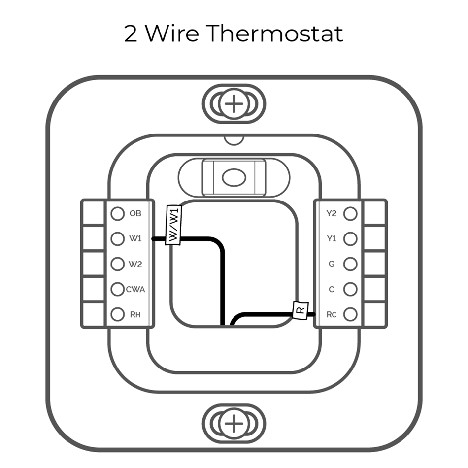
Introduction
A 2 wire heat thermostat wiring diagram symbol represents a simple electromechanical or electronic switching device used to control heating-only HVAC (Heating, Ventilation, and Air Conditioning) systems. Understanding this schematic element matters because it forms the baseline for residential climate control installation, servicing, and diagnostic procedures across North America, the UK, Europe, and Australia. Misinterpreting these schematics often leads to miswired controls, equipment short cycling, or failure of the heating appliance to energize. Proper comprehension of these symbols improves system safety, enhances troubleshooting accuracy, and ensures compliance with residential building codes.
💡 Technical Key Takeaways:
- Core Focus: Diagnostic schematic and terminal connection layout for 2 Wire Heat Thermostat Wiring Diagram Symbol.
- Target Scope: Field technicians, automotive DIYers, and residential/commercial electricians.
- Safety Rule: Always disconnect the primary power source/battery terminal and verify zero voltage with a multimeter before touching wires.
Core Concepts and Wiring Fundamentals
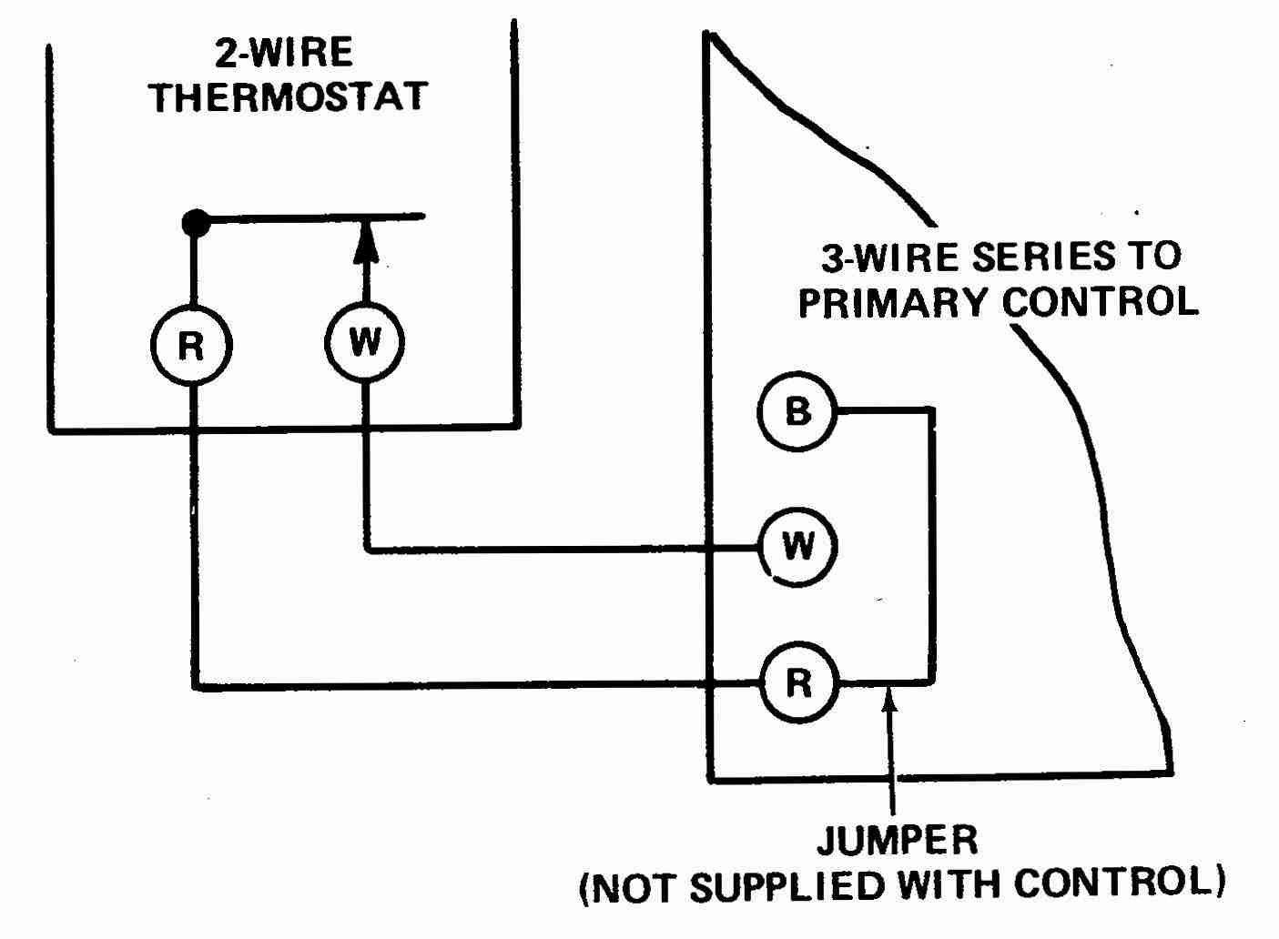
The 2 wire heating control loop operates on a very straightforward low-voltage principle, typically utilizing a 24-volt alternating current (VAC) circuit in North American setups or line-voltage configurations in specific UK and European radiant heating designs. In a standard low-voltage configuration, power originates at a step-down transformer connected to the home electrical supply. One conductor carries power to the thermostat, while the second conductor returns the switched signal back to the heating relay or gas valve gas control gas valve.
Within this circuit, the thermostat functions purely as a mechanical switch governed by a bimetallic strip or a digital temperature sensor. When ambient room temperature drops below the set point, the internal switch closes, completing the electrical loop and allowing current to flow to the heating equipment. No neutral wire is required in a traditional two-wire setup because the thermostat steals power through the closed load loop or relies entirely on self-powered battery cells for digital displays.
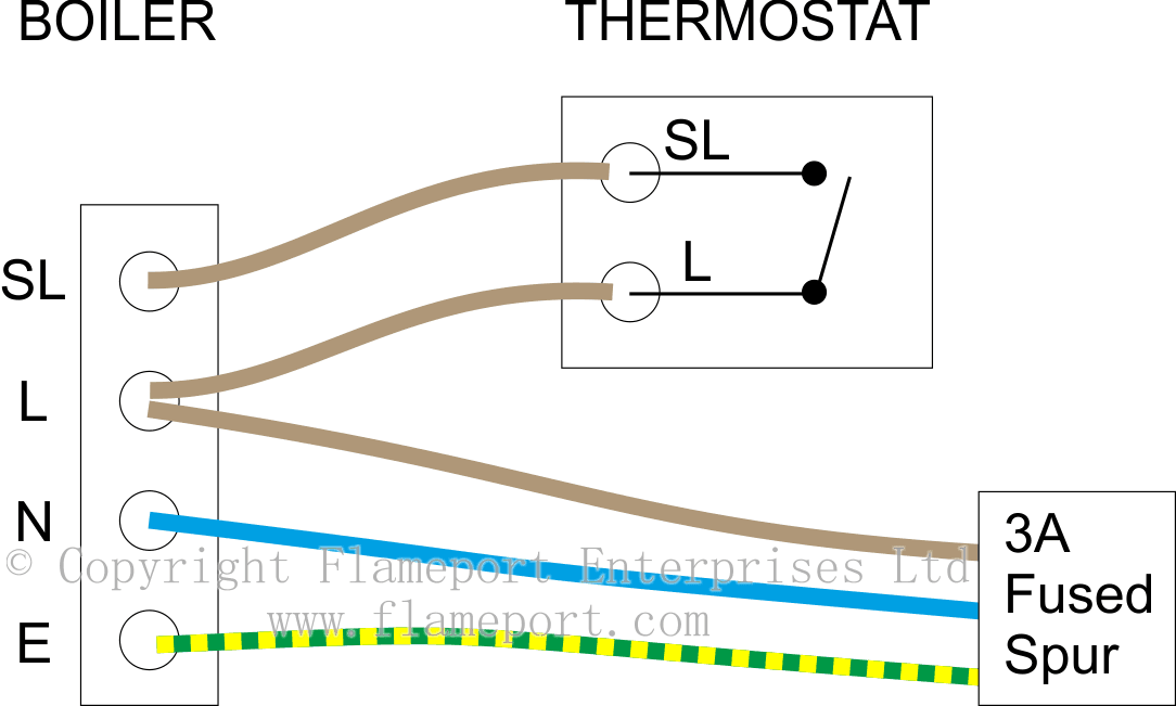
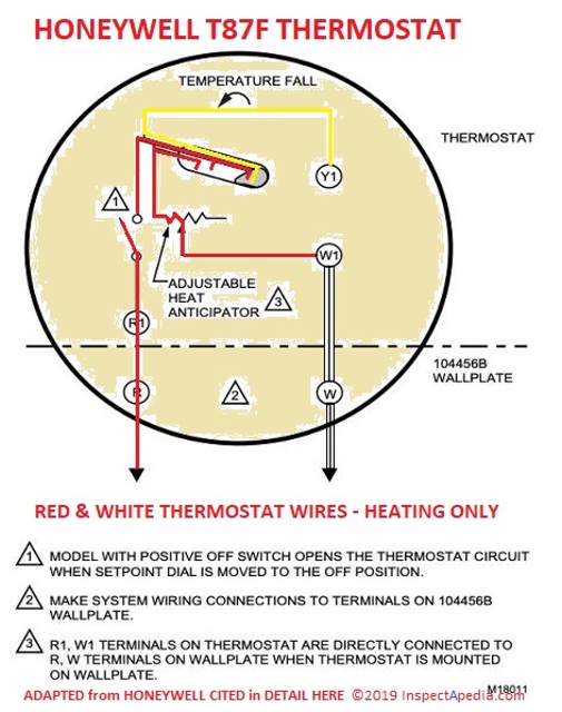
Terminal designations vary slightly by geography and manufacturer guidelines. North American equipment governed by standards such as NFPA 70 (National Electrical Code) typically labels these connections as ‘R’ (power) and ‘W’ (heat relay). In contrast, UK and Australian installations adhering to BS 7671 or AS/NZS 3000 may utilize terminals marked ‘Live’ and ‘Switched Live’ or designated numerical indicators for volt-free relay contacts. Recognizing these terminal conventions is essential before reviewing any documentation found within Home Electrical Wiring Diagrams or related technical guides.
[Finding] — According to the Electrical Safety Foundation International (ESFI), heating and thermostat equipment installation errors remain a leading cause of preventable residential electrical faults and low-voltage control failures.
Diagram Explanation and Key Components
The 2 wire heat thermostat wiring diagram symbol is typically depicted as a pair of open contacts or a simple single-pole single-throw (SPST) switch labeled with specific terminal letters. When reading a schematic, the symbol shows two incoming lines: the supply wire and the return wire. Dashed lines often denote field-installed wiring, while solid lines indicate factory-installed internal control board pathways. Standardized graphical representations follow conventions established by organizations like IEEE or IEC, ensuring technicians can interpret schematics regardless of the equipment brand.
Color coding of conductors simplifies physical installation, though technicians must always verify continuity with a multimeter rather than relying solely on jacket colors. In North America, the power wire connected to the ‘R’ terminal is traditionally red, while the wire connected to the ‘W’ terminal is white. In the UK and Europe, standard color allocations for fixed wiring follow harmonized standards where brown typically denotes live conductors and blue or black indicates neutral or switched return lines. Reviewing comprehensive references in Wiring Diagram Basics helps beginners master these fundamental layout conventions.
Each component in the diagram serves a distinct role. The transformer steps down mains voltage to a safe control voltage. The thermostat symbol acts as the environmental sensor and manual setpoint controller. The heating relay or gas valve acts as the final control element, translating the closed circuit into combustion or electrical heating output. Understanding how these symbols interact on paper prevents costly misconnections in the mechanical room.
Common Problems and Troubleshooting Methods
Typical faults in a two-wire heating circuit include open circuits, high-resistance corrosion at terminal screws, fused transformer windings, and internal switch mechanical failure. A systematic diagnostic approach begins at the equipment rather than the wall unit. Technicians should first verify that the heating system receives proper primary power and that any equipment-mounted fuses or circuit breakers remain intact. De-energize the system and verify zero energy states using a calibrated multimeter before inspecting physical connections.
When the heating system fails to activate upon a call for heat, diagnosis proceeds by bypassing the thermostat at the sub-base or terminal strip. Jumpering the power terminal directly to the heating control terminal simulates a closed thermostat switch. If the furnace or boiler fires immediately, the fault lies either in the thermostat itself or the interconnecting control wire. If the appliance still fails to ignite, the issue resides within the equipment internal control board, safety limit switches, or gas valve circuit. Technicians should consult structured diagnostic workflows found in Wiring Troubleshooting to isolate intermittent faults safely and efficiently.
Practical Tips and Safety Considerations
Working with heating control circuits requires strict adherence to safety protocols, particularly when dealing with line-voltage thermostats or integrated control systems. Always turn off the power supply at the main service panel or emergency service switch before opening equipment panels or disconnecting control wires. Even low-voltage 24VAC circuits can cause arcing or damage sensitive electronic control boards if accidentally shorted against grounded chassis metal.
Proper wire sizing and insulation integrity prevent voltage drop and erratic equipment operation over long cable runs. For standard low-voltage thermostat runs, solid copper thermostat wire rated between 18 AWG and 22 AWG is typically specified by manufacturers. Avoid running low-voltage control lines parallel to high-voltage AC power cables to prevent electromagnetic interference that can cause digital thermostat display flickering or relay chatter. Where local regulations mandate certified labor, or when working on line-voltage mains-connected thermostats, engage a licensed electrician or qualified HVAC technician to ensure compliance with local electrical safety codes.
Conclusion
Mastering the 2 wire heat thermostat wiring diagram symbol bridges the gap between theoretical electrical knowledge and practical heating system maintenance. By recognizing standardized schematic symbols, understanding low-voltage control loops, and applying systematic diagnostic procedures, technicians and DIY enthusiasts can install and service climate control equipment safely. Accurate interpretation of these diagrams prevents equipment damage and ensures reliable heating operation throughout the winter season. Further exploration of related control systems is available through resources covering Relay and Component Wiring Diagrams.
Quick Wiring Specifications & Terminal Guide
| Component / Circuit | Standard Wire Gauge | Recommended Protection |
|---|---|---|
| Control & Trigger Signals | 18 – 20 AWG | 5A – 7.5A Inline Fuse |
| Standard Auxiliary Load | 14 – 16 AWG | 15A – 20A Circuit Breaker |
| Main Power Feed / Supply | 10 – 12 AWG | 30A – 40A Heavy-Duty Relay |
Images References