Introduction
The 7 pin round semi trailer wire diagram serves as the definitive schematic guide for connecting heavy-duty commercial transport vehicles to towed units, establishing a standardized electrical interface for lighting, braking, and auxiliary power. Mastering this specific configuration ensures proper synchronization of running lights, turn signals, electric or pneumatic braking systems, and auxiliary feeds across international transport lines. Whether working on regional distribution rigs or long-haul freight equipment, technicians rely on this schematic to maintain regulatory compliance and operational safety on the highway. Correct interpretation of these schematics directly prevents lighting failures, erratic brake controller behavior, and costly roadside citations. Understanding these connections improves diagnostic accuracy and installation quality across complex 12V and 24V DC mobile power networks.
💡 Technical Key Takeaways:
- Core Focus: Diagnostic schematic and terminal connection layout for 7 Pin Round Semi Trailer Wire Diagram.
- Target Scope: Field technicians, automotive DIYers, and residential/commercial electricians.
- Safety Rule: Always disconnect the primary power source/battery terminal and verify zero voltage with a multimeter before touching wires.
Core Concepts and Wiring Fundamentals
Commercial heavy-duty transport relies on a robust electrical architecture comprising a vehicle-side socket, a multi-core multiconductor cable, and a trailer-side plug designed to withstand severe weather, road salt, and constant mechanical vibration. Power originates from the towing vehicle’s battery and alternator charging system, routed through heavy-gauge primary cables protected by circuit breakers or dedicated automotive fuses. Control signals for directional indicators, stop lamps, and marker lights are managed via dash-mounted switches and electronic control modules, while auxiliary circuits provide continuous power for liftgates, interior trailer lighting, or auxiliary battery charging banks. A solid chassis ground forms the return path for every circuit, relying on clean, unpainted metallic contact points to maintain low electrical resistance. Without an intact ground return, current will seek alternative paths through hitch components or bearing assemblies, causing intermittent electrical faults and accelerated component corrosion.
Standardization of heavy commercial vehicle connectors follows guidelines established by organizations such as the Society of Automotive Engineers (SAE) in North America, alongside equivalent regional standards in the UK, Europe, and Australasia. In North America, the standard 7-way commercial connector is frequently referred to as the SAE J560 round plug, utilizing spring-loaded lids and locking keys to secure the connection against accidental detachment. Each internal brass pin handles specific amperages, ranging from low-current marker lamp feeds up to high-amperage auxiliary and trailer ABS (Antilock Braking System) circuits. Mechanics must always disconnect the vehicle battery or isolate the main power feed before servicing high-current connectors to prevent accidental arcing, blown fuses, or damage to sensitive electronic control units.
[SAE J560] — The Society of Automotive Engineers standardizes the 7-way primary connector for heavy-duty commercial trucks and semi-trailers, ensuring interchangeability across fleets.
Diagram Explanation and Key Components
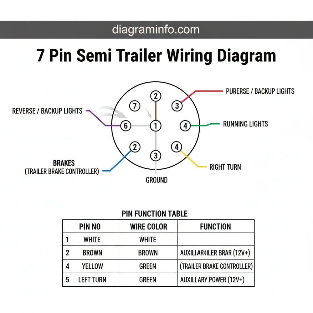
Reading a 7 pin round semi trailer wire diagram requires familiarity with standard terminal designations, numerical pin layouts, and color-coding conventions that vary slightly between jurisdictions. In the North American commercial sector using the SAE J560 standard, the seven pins are arranged in a circular configuration around a central ground or auxiliary pin, numbered one through seven or labeled by function. The standard color code typically designates white for the main system ground, black for clearance and marker lamps, yellow for the left turn signal and stop lamp, green for the right turn signal and stop lamp, red or blue for the electric trailer brakes or auxiliary stop signal, brown for tail and license plate lamps, and blue or yellow for auxiliary power or the center turn/backup circuit. For deeper insights into auxiliary mobile electronics, review additional resources on Vehicle Wiring Diagrams.
Each terminal on the schematic corresponds to a physical pin position inside the round housing, viewed from the rear wiring side or the mating face. Schematics utilize specific line types and standard automotive symbols to represent inline splices, protective boots, junction boxes, and terminal blocks mounted on the front frame rail of the trailer. Technicians must cross-reference the diagram legend to distinguish between dedicated lighting feeds and multiplexed data lines found on modern commercial equipment equipped with roll stability control and advanced braking systems. Failing to verify the exact pinout can result in cross-powered circuits, where applying the brakes accidentally illuminates the clearance lamps or triggers dashboard fault codes.
Common Problems and Troubleshooting Methods
Corrosion, physical tension from tight turning radiuses, and degraded chassis grounds represent the most frequent failure points in commercial towing electrical systems. A systematic diagnostic approach begins with a visual inspection of the physical plug and socket for green copper corrosion, bent spring pins, or cracked housing casings that allow moisture ingress. Technicians should utilize a digital multimeter set to DC voltage or a dedicated circuit tester to verify power delivery at the vehicle-side socket while an assistant operates interior switches and brake pedals. When addressing complex multi-circuit failures, exploring structured troubleshooting guides such as Wiring Troubleshooting helps isolate intermittent faults efficiently.
Open circuits and high-resistance faults often manifest as dim running lights or erratic ABS warning lamps on the dashboard. Testing involves checking voltage drop across the ground return path, as a corroded ground eyelet on the trailer frame will restrict total current flow despite showing nominal voltage on an open-circuit multimeter test. Technicians must isolate sections of the harness using jumper wires or continuity checks to determine whether the fault originates in the tractor-side receptacle, the interconnecting jumper cable, or the internal trailer wiring harness. Diagnostic procedures serve to identify the exact root cause of an electrical anomaly, but repairs must always restore factory-compliant wire gauges and secure weather-tight seals.
Practical Tips and Safety Considerations
Professional installation and maintenance of heavy vehicle wiring demand strict adherence to wire sizing, mechanical protection, and corrosion mitigation techniques. Installers should always use stranded copper automotive-grade wire rated for high-temperature engine compartments and under-chassis exposure, adhering strictly to proper ampacity limits to prevent thermal overload. Crimped terminals must be sealed with adhesive-lined heat shrink tubing to block moisture and road salts from wicking into the copper strands. For supplementary electrical components integrated into the towing setup, consulting references on Relay and Component Wiring Diagrams provides valuable insight into proper switching layouts.
A common mistake in trailer maintenance involves scraping away protective frame coating without applying a dielectric grease or corrosion inhibitor afterward, which accelerates localized rust formation and destroys the ground connection. Mechanics must also ensure service cables feature adequate service loops to prevent pinching or tension during sharp jackknife turns. Regional regulations, such as those enforced by the Federal Motor Carrier Safety Administration (FMCSA) in the US, mandate fully operational lighting and braking systems before any commercial vehicle enters public roadways. Always verify system integrity with a pre-trip inspection checklist to confirm that all circuits respond instantaneously to driver inputs.
Conclusion
Comprehending the 7 pin round semi trailer wire diagram remains an essential competency for any technician or fleet operator dealing with commercial transport equipment. Proper interpretation of pinouts, strict adherence to standardized color codes, and methodical diagnostic practices eliminate roadside delays and ensure total compliance with regional road safety standards. Maintaining clean connections, robust chassis grounds, and weather-sealed terminals extends the operational lifespan of the entire towing electrical network. Diligent application of these technical principles safeguards both equipment investments and highway travelers alike.
Quick Wiring Specifications & Terminal Guide
| Component / Circuit | Standard Wire Gauge | Recommended Protection |
|---|---|---|
| Control & Trigger Signals | 18 – 20 AWG | 5A – 7.5A Inline Fuse |
| Standard Auxiliary Load | 14 – 16 AWG | 15A – 20A Circuit Breaker |
| Main Power Feed / Supply | 10 – 12 AWG | 30A – 40A Heavy-Duty Relay |
Images References