Understanding the “4 wire light fixture wiring diagram” is fundamental for anyone involved in electrical installations, repairs, or upgrades. This specific wiring configuration, often found in modern lighting systems and ceiling fans, introduces additional control and functionality compared to simpler 2- or 3-wire setups. A solid grasp of its diagram is crucial to ensuring safe and effective operation, preventing electrical hazards, and maximizing the fixture’s potential.
Mastering the “4 wire light fixture wiring diagram” yields several significant benefits. It minimizes the risk of incorrect wiring, which can lead to short circuits, electrical fires, or damage to the connected appliance. Adhering to the wiring diagram also helps ensure compliance with local electrical codes and regulations, avoiding potential fines and safety risks. Furthermore, proficiency in diagram interpretation significantly enhances diagnostic skills, allowing for efficient troubleshooting of lighting system issues and reducing the need for costly professional assistance.
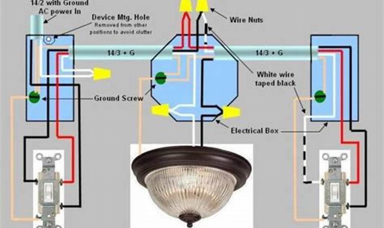
A typical “4 wire light fixture wiring diagram” includes several key components and symbols. Wire color codes are paramount: black typically represents the hot wire (power source), white represents the neutral wire, green (or bare copper) represents the ground wire, and the fourth wire, often blue or red, is used for switching or controlling additional features, such as a fan motor in a ceiling fan. The diagram illustrates the connection points between these wires, the light fixture, and the power source, including any switches or control modules. Symbols represent components like the light bulb, switch, motor, capacitor and junction boxes. Special attention should be paid to grounding symbols to ensure proper grounding, and identifying the wire connected to it. Some diagrams include fuses or relays for added safety and control.
Effective interpretation and use of the “4 wire light fixture wiring diagram” requires a systematic approach. First, identify the incoming power wires (black and white) and trace their paths to the light fixture. Next, locate the ground wire and confirm its connection to the grounding screw or terminal in the fixture and the electrical box. Finally, trace the fourth wire (often blue or red) from the switch or control module to the designated terminal on the fixture. When performing actual wiring, always disconnect the power supply at the circuit breaker before beginning any work. Double-check all connections against the diagram before restoring power to ensure accuracy and prevent potential hazards. If unsure about anything, it is always recommended to consult a qualified electrician.
To enhance understanding and accuracy, consider consulting complementary diagrams and technical manuals specific to the light fixture or appliance in question. Resources from the manufacturer are particularly valuable. Tools such as multimeters and circuit testers are essential for verifying voltage and continuity, ensuring proper circuit functionality. Additionally, reviewing general electrical wiring guides and code books can provide broader context and reinforce safety practices. Always adhere to local electrical codes and seek clarification from certified electricians when encountering unfamiliar or complex wiring scenarios.
In conclusion, mastering the “4 wire light fixture wiring diagram” offers significant advantages in terms of safety, efficiency, and cost savings. By understanding the diagram’s structure, interpreting its symbols, and applying it methodically in practical scenarios, individuals can confidently tackle electrical installations and repairs. Continued exploration of wiring diagrams and related resources will further enhance electrical knowledge and troubleshooting abilities, promoting safer and more effective electrical practices.
