Understanding automotive electrical systems is essential for both professional mechanics and avid car enthusiasts. A critical component in modern engines is the crank sensor, which provides vital information to the engine control unit (ECU). Correct connection of this sensor is paramount for proper engine operation, and deciphering its wiring diagram is a crucial skill. This article aims to demystify the connection of a four-wire crank sensor, offering a clear and concise guide to its function and wiring.
The ability to interpret and apply these diagrams translates directly into tangible benefits. Precise diagnostics become possible, reducing guesswork and saving valuable time. Correct installation, ensuring the sensor functions as intended. The knowledge gained also empowers individuals to confidently approach automotive electrical projects, whether for maintenance, repair, or performance enhancement.
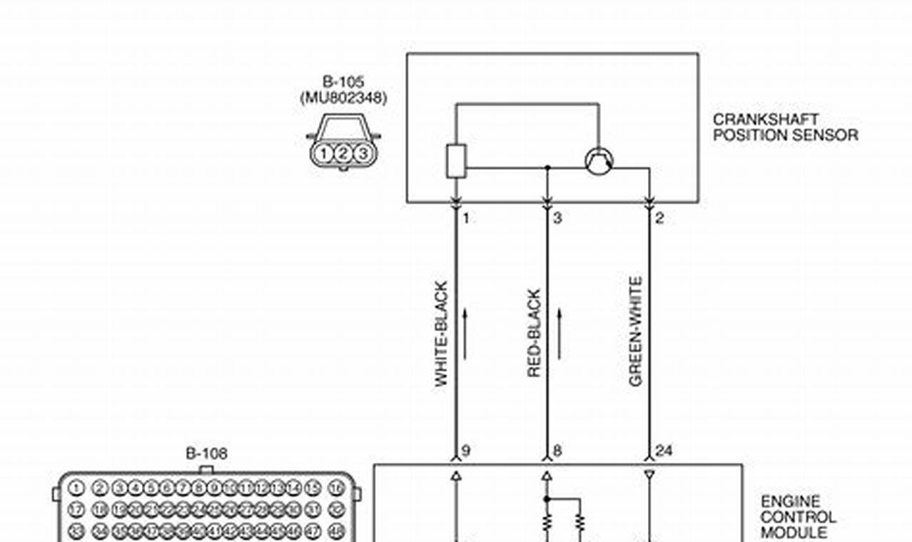
A typical diagram related to this sensor includes several key elements. Power supply lines are usually depicted with a symbol indicating voltage and polarity. Ground connections are clearly marked. Signal wires, which transmit data to the ECU, are represented with their corresponding labels. The sensor itself is shown with its four terminals, each connected to a specific point in the engine’s electrical system. Trace the lines to understand the connectivity.
Effectively reading and utilizing these diagrams involves a systematic approach. Begin by identifying the power supply and ground connections. Next, locate the signal wires and note their corresponding pin numbers on the sensor connector. Verify the wiring configuration against the vehicle’s service manual or relevant repair information. When working on the actual sensor, always disconnect the battery to prevent electrical shock and potential damage to the ECU. Use a multimeter to test continuity and voltage levels, ensuring each wire is properly connected and functioning within specified parameters. Note the diagram’s information about the sensor’s mounting location and any special installation requirements.
For further exploration, consider researching other types of automotive sensor wiring diagrams, such as those for camshaft position sensors or throttle position sensors. Online automotive forums and technical databases often provide detailed wiring schematics and troubleshooting tips. Consult reputable automotive repair manuals for comprehensive coverage of specific vehicle makes and models. Utilize online resources like AllData or Mitchell OnDemand for in-depth diagnostic information.
Mastering the interpretation and application of connection diagrams for a four-wire crank sensor is a valuable skill for anyone working with modern automotive engines. It promotes accurate diagnostics, proper installation, and ultimately, reliable engine performance. Continued learning and exploration of related wiring resources will further enhance understanding and competence in automotive electrical systems.
