Introduction
A wiring diagram for boat bow and stern lights provides the essential schematic roadmap for installing, maintaining, and repairing marine navigation lighting systems. Navigation lights are critical safety equipment required by maritime authorities worldwide to indicate a vessel’s position, heading, and status during periods of restricted visibility or darkness. Understanding these schematics ensures compliance with international collision regulations while preventing dangerous electrical failures on the water. Marine electrical systems operate under harsh environmental conditions, making proper circuit design and adherence to established schematics vital for long-term reliability. Exploring these systems forms a core part of effective Vehicle Wiring Diagrams interpretation, helping technicians master direct current applications across various types of mobile platforms.
💡 Technical Key Takeaways:
- Core Focus: Diagnostic schematic and terminal connection layout for Wiring Diagram For Boat Bow And Stern Lights.
- Target Scope: Field technicians, automotive DIYers, and residential/commercial electricians.
- Safety Rule: Always disconnect the primary power source/battery terminal and verify zero voltage with a multimeter before touching wires.
Core Concepts and Wiring Fundamentals
Marine navigation lighting systems typically operate on a 12-volt or 24-volt direct current (DC) power source supplied by the vessel’s battery bank. Power flows from the positive battery terminal through a main circuit breaker or fuse panel, routed via a dedicated switch at the helm to the respective bow and stern fixtures. Every complete electrical circuit requires a continuous path for current flow, necessitating both a positive feed wire and a negative return conductor back to the power source. Relying solely on the aluminum or fiberglass hull for the negative return is widely discouraged in modern marine construction due to galvanic corrosion and high resistance issues. Proper sizing of copper conductors prevents excessive voltage drop, which can cause incandescent navigation bulbs to dim below legal visibility thresholds.
Switches used in navigation light circuits often feature a three-position configuration (on-off-on) to control both running lights and anchor lights independently, depending on regulatory requirements. Fuses or circuit breakers must be rated strictly according to the total current draw of the connected lighting loads and the ampacity of the wire size utilized. Incorporating a Relay and Component Wiring Diagrams approach helps manage heavy loads or automated switching systems when multiple accessory lights share a single helm control input. Correctly crimped and heat-shrunk marine-grade terminals complete the physical connections, sealing out moisture to prevent internal strand oxidation.
[Finding] — According to the American Boat and Yacht Council (ABYC), the vast majority of marine electrical corrosion and intermittent failures stem from unsealed connections and improper conductor sizing exposed to moisture.
Diagram Explanation and Key Components
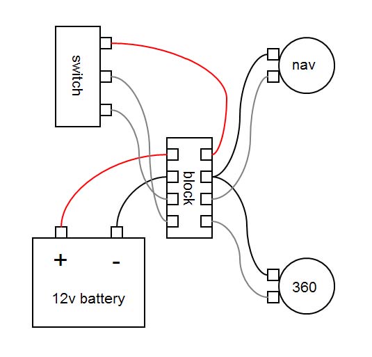
Reading a marine lighting schematic requires familiarity with standardized symbols representing batteries, fuses, single-pole single-throw switches, and specific lamp fixtures. Regional wire color standards differ significantly, requiring careful reference to local documentation; for instance, the United States Coast Guard and ABYC guidelines often utilize specific color codes such as gray with a colored stripe for navigation lights, whereas European standards under ISO 10133 dictate alternative color conventions. The schematic illustrates the bow light—typically a combination red and green sidelight or separate port and starboard fixtures—wired in parallel with the white stern light so that operating the helm switch energizes all required running lights simultaneously.
Dotted lines on a diagram usually denote physical routing boundaries or optional accessory loops, while solid lines represent actual current-carrying conductors. Junction blocks and terminal strips appear as localized cluster points where multiple branch circuits tie into the main distribution feed. Mastery of these visual elements builds upon foundational principles found in Wiring Diagram Basics, empowering technicians to trace complex harnesses from source to load without guesswork. Each symbol on the page corresponds directly to a physical piece of hardware mounted on the hull, superstructure, or dash panel.
Common Problems and Troubleshooting Methods
Systematic fault-finding begins when a navigation light fails to illuminate, often pointing to localized corrosion, a blown fuse, or a compromised ground connection. Technicians must first verify power output at the helm switch using a digital multimeter set to DC voltage before moving downstream toward the bow and stern fixtures. Finding battery voltage at the switch but zero volts at the lamp socket indicates an open circuit, which may stem from a damaged wire run, a loose butt connector, or an oxidized fuse holder. Conversely, low voltage readings at the lamp typically highlight high resistance caused by corrosion within the conductor strands or a failing ground path.
Intermittent operation usually reveals itself during vessel movement, pointing toward mechanical stress on wire harnesses routed through tight bulkheads or hinges. Applying structured diagnostic workflows rooted in Wiring Troubleshooting enables technicians to isolate faults efficiently by splitting the circuit into manageable testing segments. Continuity checks performed with the power safely disconnected help locate broken internal copper strands hidden beneath seemingly intact insulation layers. Never assume a newly installed LED replacement bulb functions correctly until polarity and driver compatibility are thoroughly confirmed with test equipment.
Practical Tips and Safety Considerations
Safety remains paramount when working on marine electrical architectures, requiring the complete de-energization of the system by disconnecting the battery banks before cutting or modifying any conductors. Standard practices dictate the exclusive use of tinned copper marine-grade wire (Type tinned OFC), which resists the destructive oxidation process common in humid saltwater environments. Standard automotive wire lacks the necessary corrosion resistance and will degrade rapidly inside a marine hull. Heat-shrink tubing featuring an adhesive lining must be shrunk over every crimped connection to create a watertight, strain-relieved seal.
Adhering to regional standards such as ABYC E-11 in the US or equivalent international maritime codes ensures that installations meet rigorous safety benchmarks regarding overcurrent protection and fire prevention. Common installation errors include routing delicate lighting wires alongside high-current engine starter cables, which introduces electromagnetic interference and potential chafing hazards. Proper zip-tie spacing and protective chafing gear safeguard wire runs against constant hull vibration. Reviewing broader documentation resources such as General and Miscellaneous Wiring Diagrams provides additional perspective on handling auxiliary vehicle and vessel accessory circuits safely.
Conclusion
Mastering the schematic layout for vessel navigation lighting empowers owners and technicians to maintain reliable systems that ensure nighttime safety on the water. Diligent attention to wire sizing, color coding, corrosion protection, and systematic testing prevents frustrating electrical failures far from shore. Adhering to recognized marine electrical standards guarantees professional results and long-term durability across all aquatic environments. Review the complete collection of wiring schematics and diagnostic guides today to improve marine electrical installation accuracy.
Quick Wiring Specifications & Terminal Guide
| Component / Circuit | Standard Wire Gauge | Recommended Protection |
|---|---|---|
| Control & Trigger Signals | 18 – 20 AWG | 5A – 7.5A Inline Fuse |
| Standard Auxiliary Load | 14 – 16 AWG | 15A – 20A Circuit Breaker |
| Main Power Feed / Supply | 10 – 12 AWG | 30A – 40A Heavy-Duty Relay |
Images References