Introduction
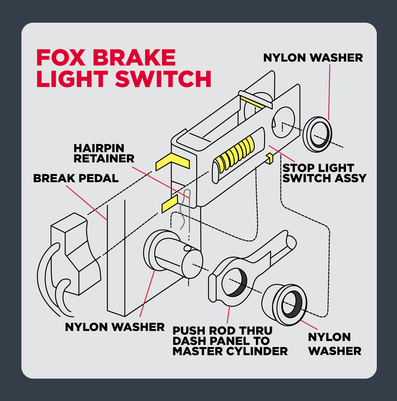
The structure of brake light switch diagram outlines the electrical pathways responsible for activating rear stop lamps whenever the brake pedal is depressed. Understanding this schematic layout matters greatly because a failing brake lamp circuit compromises road safety, invites regulatory fines, and can disrupt modern vehicle features such as cruise control cancellation and shift lock mechanisms. This configuration is used universally across 12-volt and 24-volt direct current automotive electrical systems found in passenger cars, commercial transport, and heavy machinery across the US, UK, Canada, and Australia. Mastering the blueprint improves troubleshooting accuracy, reduces diagnostic time, and guarantees proper circuit restoration during component replacement.
💡 Technical Key Takeaways:
- Core Focus: Diagnostic schematic and terminal connection layout for Structure Of Brake Light Switch Diagram.
- Target Scope: Field technicians, automotive DIYers, and residential/commercial electricians.
- Safety Rule: Always disconnect the primary power source/battery terminal and verify zero voltage with a multimeter before touching wires.
Core Concepts and Wiring Fundamentals
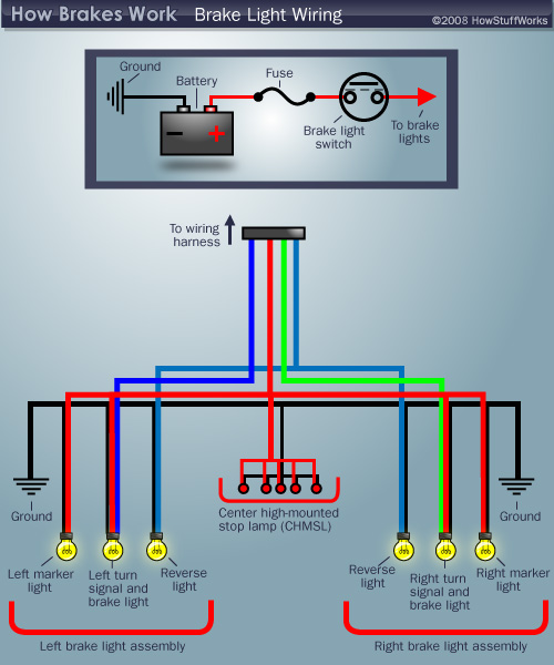
Vehicle stop lamp systems operate on a direct current low-voltage architecture governed by standards set by organizations like the Society of Automotive Engineers. The fundamental loop consists of a battery power source, a protective fuse, the mechanical brake pedal switch, terminal connectors, and the rear bulb or light-emitting diode assemblies. Power typically routes from the battery through a dedicated fuse in the interior or under-hood distribution panel before reaching the switch input terminal. When the pedal rests, mechanical pressure keeps the internal contacts open, blocking current flow to the load.
Depressing the brake pedal releases the plunger, allowing internal spring-loaded contacts to close and route electricity downstream toward the rear lamps. Modern vehicles often incorporate dual-circuit switches, housing both a normally open contact set for the stop lamps and a normally closed or secondary contact set for the powertrain control module. This dual function communicates driver intent to multiple onboard computers, affecting transmission shifting, electronic stability control, and regenerative braking systems. Recognizing these multi-pole configurations is essential when reviewing Vehicle Wiring Diagrams during diagnostic procedures.
[Finding] — According to National Highway Traffic Safety Administration data, stop lamp failures contribute significantly to rear-end collisions, making precise circuit maintenance and diagnostic accuracy vital for highway safety.
Diagram Explanation and Key Components
Reading the structure of brake light switch diagram requires familiarity with standardized automotive schematic symbols, wire color codes, and terminal identification numbers. Schematics typically depict the switch in its unactuated, rest position with battery voltage marked at the input feed, often designated as terminal thirty or ignition feed depending on manufacturer conventions. Output wires lead away from the switch toward the chassis harness, split at junction blocks, and terminate at the left and right rear lamp assemblies. Wire colors vary significantly by region and manufacturer; North American vehicles often utilize green with red stripes, while European and British models governed by standard practices may feature entirely different trace color designations.
Component symbols on the diagram indicate whether the switch operates via mechanical plunger, hydraulic pressure, or electronic Hall-effect sensors. Dashed lines surrounding individual terminals denote a single physical switch housing containing multiple independent circuits. Correlating these schematic symbols with the physical components requires studying Relay and Component Wiring Diagrams to understand how control signals translate into high-current lamp activation. Every wire segment carries a specific gauge recommendation and circuit identification number stamped directly onto the insulation jacket at regular intervals.
Common Problems and Troubleshooting Methods
Diagnostic evaluation of stop lamp malfunctions begins with a systematic voltage-drop test across the switch input and output terminals rather than random component swapping. Typical failures include internal contact erosion, misadjusted switch plungers resulting in constantly illuminated lamps or complete non-operation, blown fuses due to short circuits in the rear harness, and corroded ground points. A structured diagnostic approach dictates first verifying fuse integrity with a digital multimeter or test light. Next, technicians check for battery voltage at the switch feed wire with the key in the appropriate position.
If voltage is present at the input but fails to pass through to the output when the pedal is depressed, the internal switch contacts have failed internally, or the physical actuator alignment is incorrect. Conversely, if voltage passes through the switch but the rear lamps remain dark, the fault lies further downstream in the chassis wiring, bulb sockets, or common ground connections. Reviewing Wiring Troubleshooting guides helps streamline this fault-finding process, ensuring every segment from the fuse panel to the bulb filament is evaluated methodically without unnecessary disassembly.
Practical Tips and Safety Considerations
Working on automotive electrical architectures demands strict adherence to safety protocols, including disconnecting the negative battery terminal before probing sensitive circuits or replacing fused links. Technicians must always verify circuit de-energization using a calibrated digital multimeter before disconnecting harness connectors or back-probing terminals. Avoid piercing wire insulation with sharp test probes, as moisture ingress later leads to copper corrosion, high resistance, and intermittent electrical faults. When replacing faulty switches, ensure the plunger height is adjusted precisely according to manufacturer specifications to prevent premature switch wear or brake drag.
Use proper wire strippers, heat-shrink butt connectors, and OE-grade locking terminals for any necessary harness repairs to withstand continuous vehicle vibration and thermal cycling. Mechanics must also consult regional service information to verify whether recalibration of steering angle or brake pressure sensors is required after switch replacement. For broader foundational knowledge regarding schematic symbols, line weights, and cross-references, refer to Wiring Diagram Basics before tackling complex multi-system harnesses.
Conclusion
Mastering the structure of brake light switch diagram empowers technicians and enthusiasts alike to diagnose complex electrical faults with confidence and precision. By breaking down power feeds, switch contacts, control modules, and rear load circuits into manageable segments, accurate diagnosis replaces guesswork. Safety vigilance, proper tool utilization, and strict adherence to manufacturer specifications ensure long-term reliability and roadworthiness. Maintaining a thorough understanding of these fundamental principles ultimately safeguards vehicle occupants and keeps modern transportation networks running safely.
Quick Wiring Specifications & Terminal Guide
| Component / Circuit | Standard Wire Gauge | Recommended Protection |
|---|---|---|
| Control & Trigger Signals | 18 – 20 AWG | 5A – 7.5A Inline Fuse |
| Standard Auxiliary Load | 14 – 16 AWG | 15A – 20A Circuit Breaker |
| Main Power Feed / Supply | 10 – 12 AWG | 30A – 40A Heavy-Duty Relay |
Images References