Introduction
A simple vehicle headlight circuit is the foundational electrical pathway that delivers direct current power from a 12V or 24V mobile electrical source to forward illumination lamps. Mastering this architecture matters because reliable nighttime visibility depends on low-resistance connections, correctly rated protection devices, and robust switching mechanisms. This fundamental arrangement appears across older passenger cars, vintage motorcycles, and heavy machinery, serving as the blueprint for understanding more complex modern lighting networks. Comprehending how voltage travels from the battery through the control switch and out to the bulb filaments improves diagnostic accuracy and prevents electrical fires. Working on mobile power grids requires disconnecting the negative battery terminal before servicing any high-current component to eliminate unexpected short circuits and arc flashes.
💡 Technical Key Takeaways:
- Core Focus: Diagnostic schematic and terminal connection layout for Simple Vehicle Headlight Circuit.
- Target Scope: Field technicians, automotive DIYers, and residential/commercial electricians.
- Safety Rule: Always disconnect the primary power source/battery terminal and verify zero voltage with a multimeter before touching wires.
Core Concepts and Wiring Fundamentals
Vehicle headlight circuits operate on a closed-loop direct current architecture utilizing the metal chassis as a shared return path, commonly referred to as a chassis ground. Power originates at the battery or alternator, flows through a fusible link or primary fuse panel, travels to the dashboard switch or a dedicated control relay, and finally reaches the headlight bulb. The physical conductors consist of stranded copper wire sized according to current draw and voltage drop limits specified by the Society of Automotive Engineers or regional equivalents. Terminal connectors must maintain tight mechanical pressure and environmental sealing to prevent oxidation from creeping into the copper strands.
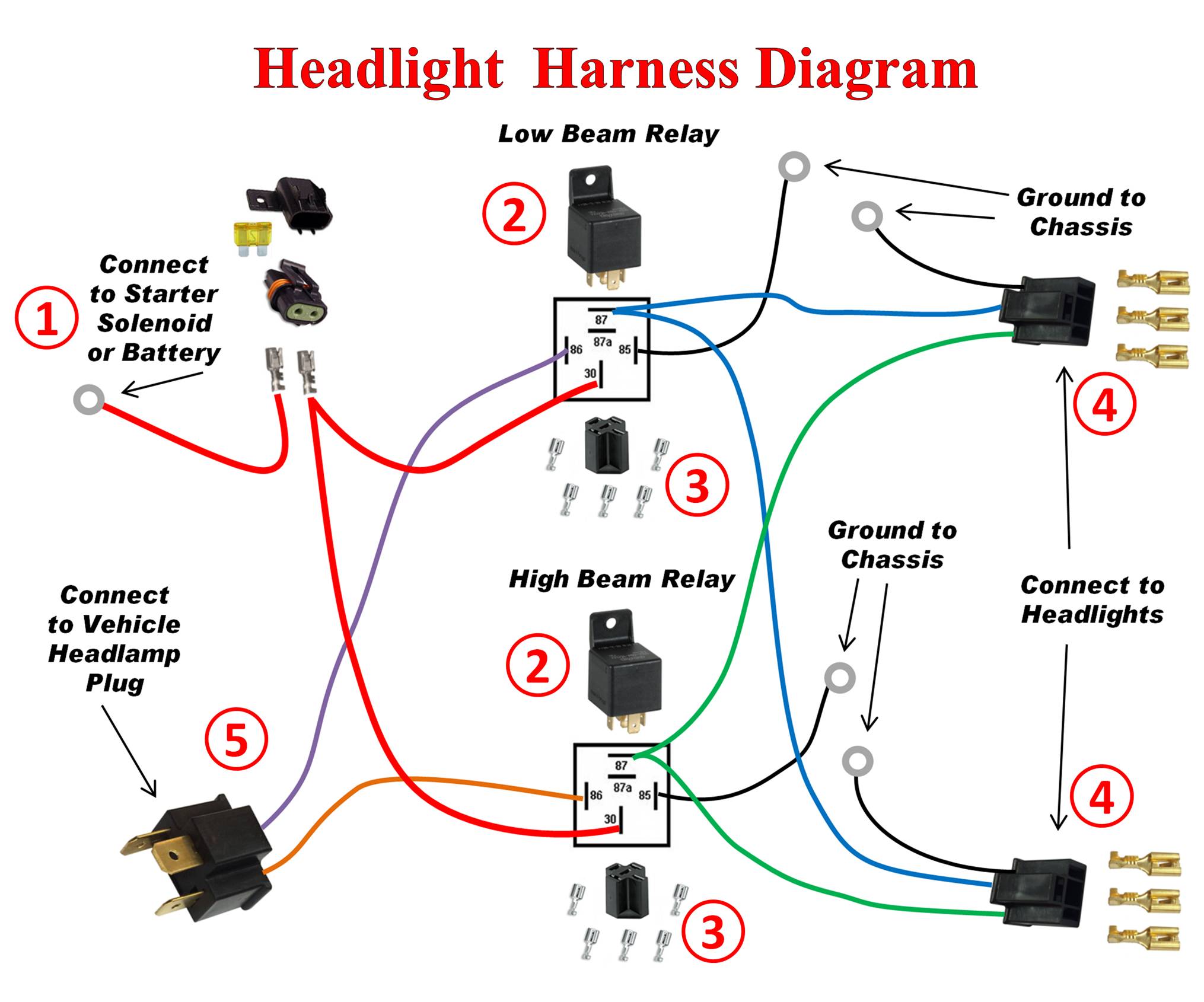
Most traditional automotive configurations employ mechanical relays to handle high electrical loads while keeping heavy-gauge wiring out of the passenger compartment. When the dashboard switch closes, a low-current control circuit energizes the relay coil, pulling a heavy-duty internal contact closed. This secondary load circuit then routes full battery voltage directly to the lamp filaments, minimizing line resistance and preventing switch degradation. Understanding these distinct loops is essential when reviewing Relay and Component Wiring Diagrams during diagnostic procedures.
[Automotive Lighting Standards] — Society of Automotive Engineers (SAE) specifications govern headlight performance, circuit protection parameters, and wire gauge selection to ensure safe operation across standard vehicle operating temperatures.
Diagram Explanation and Key Components
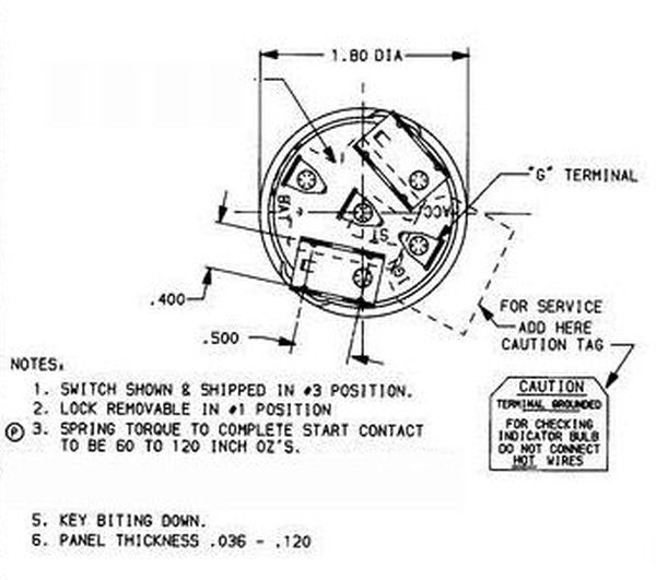
Schematics representing a simple vehicle headlight circuit use standardized symbols to denote batteries, fuses, single-pole double-throw switches, dual-filament bulbs, and chassis grounds. Line types differentiate between heavy-gauge power feeds and thin control wires, while alphanumeric codes indicate wire colors and terminal pin designations. Regional color standards vary significantly; for instance, older North American wiring often utilizes distinct hues for high and low beams, whereas British and European networks frequently rely on specific base colors combined with tracer stripes governed by standards like BS AU 7. Analyzing these schematics alongside Wiring Diagram Basics allows technicians to quickly trace current paths from source to load.
The primary components include the power supply, overcurrent protection devices, control switches, relays, wiring harnesses, and the lamp assemblies themselves. Dual-filament bulbs feature separate terminals for low-beam and high-beam operation, sharing a common ground connection. A break in any of these individual component connections interrupts the entire flow, resulting in an inoperative lamp. Recognizing how each symbol translates to physical hardware under the hood prevents misinterpretation of schematic lines.
Common Problems and Troubleshooting Methods
Systematic fault-finding in a vehicle lighting setup requires a logical methodology to isolate open circuits, high-resistance connections, and short-to-ground conditions. Typical failure points include corroded bulb sockets, melted harness connectors due to excessive bulb wattage, and fractured chassis ground straps. Technicians frequently encounter blown fuses caused by pinched wires rubbing against sharp sheet metal edges. Approaching these symptoms with a structured Wiring Troubleshooting workflow ensures accurate diagnosis without unnecessary part replacement.
Diagnostic testing begins with a visual inspection of the fuse and bulb filaments, followed by voltage drop testing using a digital multimeter across active circuits under load. Probing the circuit while it is energized reveals high-resistance points that appear normal under static, zero-current conditions. If a headlight fails to illuminate, checking voltage at the bulb plug determines whether the fault lies on the power supply side or the ground return path. Mechanics should never rely solely on continuity beeps, as low-current meter settings can register continuity through high-resistance corrosion that fails completely under real electrical loads.
Practical Tips and Safety Considerations
Maintaining integrity in mobile electrical systems demands proper crimping tools, heat-shrink tubing with adhesive lining, and correct wire gauge selection. Twisting wires together and wrapping them in standard electrical tape invites moisture infiltration, copper oxidation, and subsequent circuit failure. When replacing blown fuses, always install the exact amperage rating specified by the manufacturer; substituting a higher-rated fuse creates a severe fire hazard by allowing dangerous overcurrent conditions to melt the surrounding harness insulation. Technicians should consult Vehicle Wiring Diagrams specific to the exact make, model, and year before splicing into factory harnesses.
Conclusion
Grasping the fundamentals of a simple vehicle headlight circuit empowers DIY enthusiasts and professional technicians alike to maintain safe, reliable mobile lighting systems. Respecting direct current principles, utilizing proper diagnostic tools, and adhering to established manufacturing standards prevent recurring electrical faults. Systematic verification of power feeds, switching devices, and ground paths ensures long-term dependability across any automotive application. Further exploration into related topics can be found by examining comprehensive Home Electrical Wiring Diagrams to understand parallel power distribution concepts.
Quick Wiring Specifications & Terminal Guide
| Component / Circuit | Standard Wire Gauge | Recommended Protection |
|---|---|---|
| Control & Trigger Signals | 18 – 20 AWG | 5A – 7.5A Inline Fuse |
| Standard Auxiliary Load | 14 – 16 AWG | 15A – 20A Circuit Breaker |
| Main Power Feed / Supply | 10 – 12 AWG | 30A – 40A Heavy-Duty Relay |
Images References