Introduction
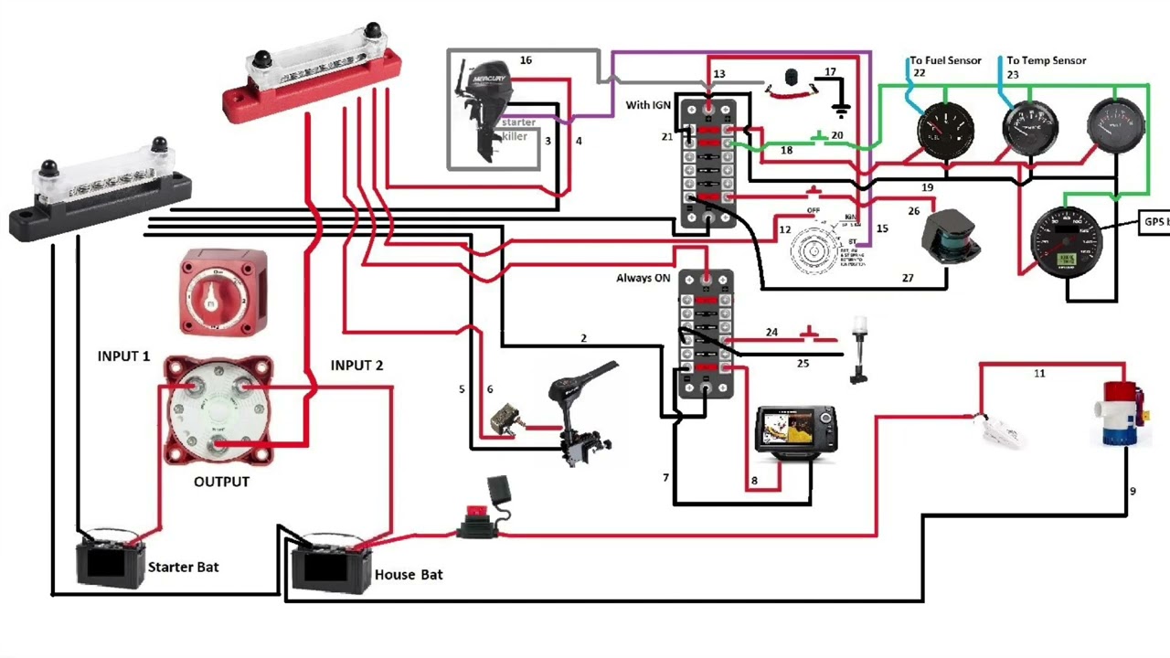
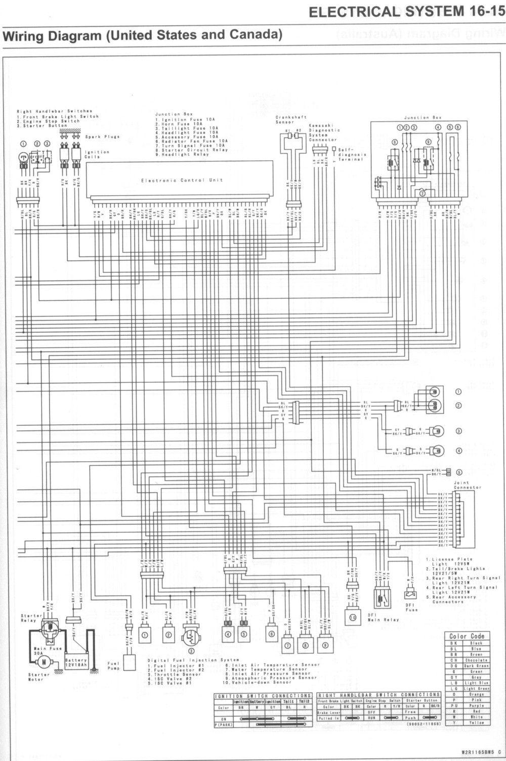
A motorcycle toggle switch wiring diagram is a graphical blueprint mapping out electrical connections for aftermarket accessories, auxiliary lights, or custom ignition controls on two-wheeled motor vehicles. Mastering this schematic ensures proper integration of 12V DC systems, preventing catastrophic electrical fires, blown fuses, and drained batteries. Technicians and DIY builders rely on these technical drawings to interpret power sources, control circuits, and load paths accurately. Proper documentation bridges the gap between raw hardware and reliable street operation, particularly when customizing or troubleshooting complex harnesses found across modern and vintage machines. For broader applications involving auxiliary control circuits, reviewing Relay and Component Wiring Diagrams provides helpful foundational context.
💡 Technical Key Takeaways:
- Core Focus: Diagnostic schematic and terminal connection layout for Motorcycle Toggle Switch Wiring Diagram.
- Target Scope: Field technicians, automotive DIYers, and residential/commercial electricians.
- Safety Rule: Always disconnect the primary power source/battery terminal and verify zero voltage with a multimeter before touching wires.
Core Concepts and Wiring Fundamentals
Vehicle electrical systems operate on direct current, utilizing a closed loop comprising a power source, protection devices, switching components, and a functional load. The battery supplies nominal voltage, while a fuse or circuit breaker acts as the primary safety device, interrupting current flow during an overload or short circuit. Automotive and motorcycle electrical architectures typically rely on the metal frame as a common negative return path, though dedicated chassis ground wires offer superior reliability against corrosion and vibration resistance.
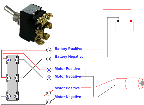
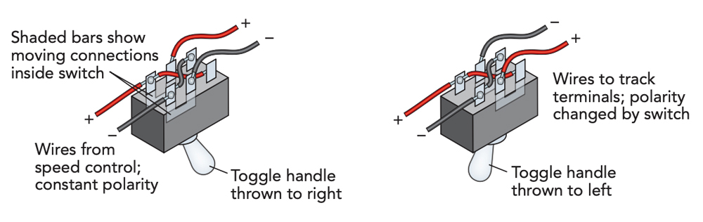
Toggle switches serve as manual actuators to open or close these circuits, categorized primarily by pole and throw configurations such as Single-Pole Single-Throw (SPST) or Double-Pole Double-Throw (DPDT). High-current accessories, such as auxiliary driving lamps or heated grips, demand the integration of an electromechanical relay. Directing heavy operating currents through a miniature toggle switch invariably leads to melted contacts, voltage drop, and switch failure; instead, the switch controls a low-current trigger circuit that commands the relay power contacts.
[Vibration and Thermal Fatigue] — According to the Society of Automotive Engineers (SAE), continuous mechanical vibration and cyclic thermal expansion represent the leading mechanical stressors causing high-resistance faults in mobile electrical connections.
Diagram Explanation and Key Components
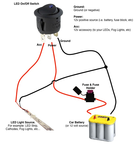
Interpreting a motorcycle toggle switch wiring diagram requires understanding standardized schematic symbols, line weights, and color-coding conventions established by automotive engineering practices. Solid lines represent primary power-carrying conductors, while dashed lines frequently indicate mechanical linkages, chassis grounding points, or optional sub-circuits. Standard switch terminals are designated as power input (often labeled Supply or Battery), switched output (Load), and chassis return (Ground, if the toggle features an internal indicator LED).
Color codes vary significantly by manufacturing region and aftermarket brand. In North America (following conventions influenced by SAE standards), black frequently denotes ground, red indicates unfused battery power, and orange or yellow signifies switched auxiliary power. In contrast, British and Commonwealth machines adhering to traditional BS standards often use brown for live feeds and blue for neutral or ground paths. Consulting the specific equipment manufacturer documentation remains mandatory before cutting into any factory harness.
Common Problems and Troubleshooting Methods
Systematic fault-finding begins with visual inspection and progresses to multimeter testing to isolate intermittent opens, high-resistance connections, and direct shorts to ground. When an auxiliary accessory fails to activate, the diagnostic sequence starts at the load component, verifying continuity and ground integrity before working backward through the relay and toggle switch contacts. A blown inline fuse immediately points toward a short circuit within the downstream wiring harness or an overloaded accessory drawing excessive amperage.
Corrosion inside toggle switch housings frequently causes voltage drop, characterized by dim lighting or intermittent operation when riding over rough road surfaces. Technicians utilize a digital multimeter set to DC voltage to measure potential drop across closed switch terminals; any reading above 0.2 volts under active load indicates degraded internal contacts requiring replacement. For related diagnostic procedures, refer to Wiring Troubleshooting guides.
Practical Tips and Safety Considerations
Safe installation practices require disconnecting the negative battery terminal before modifying any vehicle electrical circuit to prevent accidental arcing and component damage. Wire gauge selection must match the continuous current draw of the connected load, utilizing appropriately sized copper stranded conductors rated for automotive temperature ranges and oil resistance. Crimp terminals should be secured with calibrated ratcheting tools, followed by adhesive-lined heat shrink tubing to seal joints against moisture ingress and road salt corrosion.
Routing wires away from exhaust headers, moving steering components, and sharp frame edges prevents chafing and catastrophic insulation failure over time. Securing harnesses with UV-resistant cable ties at regular intervals eliminates destructive vibration fatigue. For comprehensive reference on standard vehicle integration techniques, review Vehicle Wiring Diagrams to maintain professional installation standards.
Conclusion
Analyzing a motorcycle toggle switch wiring diagram empowers technicians and enthusiasts to install auxiliary equipment safely, diagnose faults efficiently, and maintain reliable electrical system performance. Respecting electrical load limits, employing proper fusing, and protecting connections against environmental factors guarantee long-term durability on the road. Diligent adherence to manufacturer specifications and recognized automotive standards ensures every custom wiring modification operates safely and predictably.
Quick Wiring Specifications & Terminal Guide
| Component / Circuit | Standard Wire Gauge | Recommended Protection |
|---|---|---|
| Control & Trigger Signals | 18 – 20 AWG | 5A – 7.5A Inline Fuse |
| Standard Auxiliary Load | 14 – 16 AWG | 15A – 20A Circuit Breaker |
| Main Power Feed / Supply | 10 – 12 AWG | 30A – 40A Heavy-Duty Relay |
Images References