Introduction
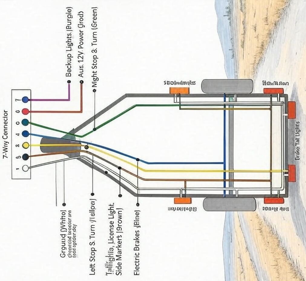
A led trailer tail lights diagram serves as the master blueprint for routing electrical current from a tow vehicle to a towed load, ensuring compliance with lighting regulations and road safety standards. This visual schematic maps out 12V and 24V direct current (DC) circuits, clarifying how power, ground paths, and control signals interact across standard plug configurations. Understanding these schematics improves installation quality, prevents blown fuses, and ensures that brake lamps, turn signals, and running lights operate reliably in all weather conditions. Whether setting up a utility trailer, a boat hauler, or a heavy commercial unit, accurate interpretation of these diagrams prevents costly miswirings and intermittent lighting faults.
💡 Technical Key Takeaways:
- Core Focus: Diagnostic schematic and terminal connection layout for Led Trailer Tail Lights Diagram.
- Target Scope: Field technicians, automotive DIYers, and residential/commercial electricians.
- Safety Rule: Always disconnect the primary power source/battery terminal and verify zero voltage with a multimeter before touching wires.
Core Concepts and Wiring Fundamentals
Trailer lighting systems rely on a closed DC circuit powered by the towing vehicle’s alternator and battery, protected by dedicated fuses located in the primary vehicle fuse box. Voltage typically runs at 12 volts for standard passenger vehicles and light commercial trucks, though heavy-duty equipment may utilize 24-volt systems. Electrical energy travels from the dashboard switches, through a multi-pin trailer connector, along the chassis frame via protected wire bundles, and terminates at the specific lamp assemblies.
Light Emitting Diodes (LEDs) require strict attention to polarity compared to old incandescent bulbs, meaning positive and negative lines must never be reversed. A ground wire, often routed directly back to the tow vehicle or secured cleanly to a bare metal frame point, completes the circuit loop. Without a low-resistance ground return path, current will find alternative, unintended routes through hitch components, leading to erratic flashing, dim illumination, or total system failure. Consult Vehicle Wiring Diagrams for deeper insight into how auxiliary tow harnesses integrate with factory body control modules.
[Finding] — According to the National Highway Traffic Safety Administration (NHTSA), lighting and signal failures represent a leading mechanical cause of rear-end collisions involving towed units.
Diagram Explanation and Key Components
Schematics for led trailer tail lights diagram layouts use standardized lines, symbols, and color-coded insulation to represent physical conductors. Color coding varies significantly by region, with standard North American layouts using brown for running lights, yellow for left turn and stop, green for right turn and stop, and white for the main chassis ground. Conversely, European and Australian setups often adhere to ISO 1724 or ISO 11446 specifications, utilizing different conductor colors like black, blue, and red for auxiliary feeds.
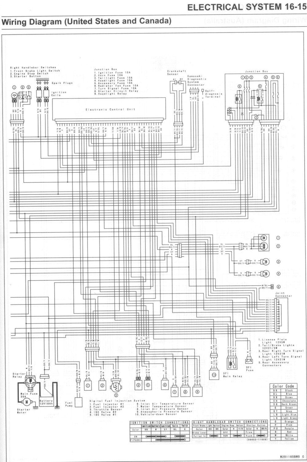
Reading these diagrams requires recognizing symbols for male and female connector pins, splices, fused links, and multi-function light clusters. Modern LED fixtures often incorporate integrated circuit boards that combine stop, tail, and turn functions into shared diode arrays, managed internally by micro-resistors or distinct input leads. Reviewing Wiring Diagram Basics helps beginners decode standard line weights, open/closed switch symbols, and connector pin numbering conventions found on major manufacturer specification sheets.
Common Problems and Troubleshooting Methods
Systematic fault-finding for LED trailer illumination requires a structured diagnostic approach using a digital multimeter or a dedicated 12V test light. Typical field failures include rusted connector pins, corroded frame ground points, pinched harness jackets, and moisture ingress inside unsealed lamp housings. Because LEDs draw significantly less current than incandescent bulbs, some older vehicle flasher relays fail to cycle properly, causing rapid hyper-flashing or no flash at all until load resistors are installed.
When troubleshooting an inactive light cluster, technicians should first verify battery voltage at the vehicle-side socket using a multimeter set to DC volts. Next, check the continuity of the ground wire from the light housing back to the tow vehicle chassis, as open grounds account for the vast majority of erratic dual-filament LED behavior. Mechanics must systematically test each circuit segment from front to back, verifying that isolation and insulation remain intact along exposed frame rails. For advanced testing methodologies, refer to Wiring Troubleshooting to isolate complex intermittent faults.
Practical Tips and Safety Considerations
Always disconnect the tow vehicle’s negative battery terminal before cutting, splicing, or servicing heavy electrical harnesses to prevent accidental short circuits and blown fuses. Vehicle high-current work demands proper wire gauge selection, typically 16 AWG or 14 AWG copper wiring for standard trailer runs, ensuring the conductors can handle cumulative electrical loads without excessive voltage drop. Technicians should always seal wire splices using adhesive-lined heat shrink tubing to prevent moisture corrosion from destroying copper strands.
A frequent field mistake involves relying on the physical ball hitch to carry the system ground return, which results in high resistance as grease, dirt, and rust accumulate between the metal surfaces. Always run a dedicated white ground wire from the tow vehicle plug directly to the trailer frame and individual light mounting bolts. Where local regulations or commercial payload capacities apply, installations must conform strictly to standards set by the Society of Automotive Engineers (SAE) or applicable regional road transport authorities.
Conclusion
Mastering a led trailer tail lights diagram transforms complex automotive electrical networks into manageable, logical circuits that guarantee optimal road visibility. By respecting polarity requirements, maintaining robust low-resistance grounds, and utilizing proper sealing techniques, DIY enthusiasts and professional technicians alike can achieve permanent, weather-resistant installations. Careful adherence to schematic guidelines and systematic diagnostic steps ensures reliable operation across every hauling application, protecting both cargo and fellow motorists on the highway.
Quick Wiring Specifications & Terminal Guide
| Component / Circuit | Standard Wire Gauge | Recommended Protection |
|---|---|---|
| Control & Trigger Signals | 18 – 20 AWG | 5A – 7.5A Inline Fuse |
| Standard Auxiliary Load | 14 – 16 AWG | 15A – 20A Circuit Breaker |
| Main Power Feed / Supply | 10 – 12 AWG | 30A – 40A Heavy-Duty Relay |
Images References