Introduction
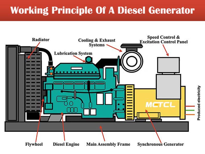
A generator engine switch diagram serves as the master blueprint for controlling the starting, running, and stopping functions of an internal combustion engine-driven electrical generator. Portable and standby generators rely heavily on these control circuits to govern ignition timing, fuel solenoid activation, and starter motor engagement. Understanding this specific schematic improves diagnostic accuracy, prevents costly miswirings, and ensures that safety interlocks function correctly during emergency power outages. Whether dealing with a recreational inverter unit or a heavy-duty industrial backup system, technicians and hobbyists must interpret these control schemas accurately. For further study on internal device controls, consult resources covering Appliance and Device Wiring to expand diagnostic methodologies.
💡 Technical Key Takeaways:
- Core Focus: Diagnostic schematic and terminal connection layout for Generator Engine Switch Diagram.
- Target Scope: Field technicians, automotive DIYers, and residential/commercial electricians.
- Safety Rule: Always disconnect the primary power source/battery terminal and verify zero voltage with a multimeter before touching wires.
Core Concepts and Wiring Fundamentals
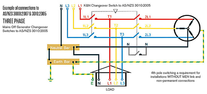
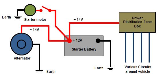
Portable and standby generator systems typically utilize a low-voltage direct current (DC) control circuit—usually 12V derived from a starting battery or a stator charging winding—to manage high-voltage alternating current (AC) power generation. The engine switch itself acts as an electromechanical gatekeeper, completing or interrupting specific paths to ground or power depending on its position. In an “OFF” position, the switch typically grounds the ignition magneto coil to kill the spark, while simultaneously opening the circuit to the fuel shutoff solenoid. In a “RUN” position, the ground path is lifted, and control power flows to the automatic voltage regulator and fuel delivery systems. In a “START” position, the momentary contact bridges power from the battery directly to the starter motor solenoid.
Circuit protection within these systems generally relies on inline glass or blade fuses that shield the sensitive control module and charging circuit from short circuits. Relays often bridge the gap between the low-amperage dash switch and the high-amperage starter motor draw, preventing switch contact welding. Ground integrity remains paramount across the engine block, frame, and control panel. A compromised ground path introduces high resistance, resulting in intermittent starting failures, clicking starter solenoids, or erratic engine behavior that mirrors deeper mechanical faults.
[Finding] — According to the Consumer Product Safety Commission (CPSC), portable generator carbon monoxide and electrical safety incidents frequently stem from improper installation, bypassed interlocks, or neglected maintenance on engine control switches and wiring harnesses.
Diagram Explanation and Key Components
Reading a generator engine switch diagram requires familiarity with standardized schematic symbols, such as SPST (Single-Pole Single-Throw) and multi-position rotary switch grids. Symbols represent the physical terminals on the switch, often labeled with letters like B (Battery), S (Starter), Ignition (I), Ground (G or GND), and Accessory (ACC). Dashed lines on the schematic usually indicate mechanical linkage between different poles of the same switch, showing how a single turn affects multiple independent circuits simultaneously. Line types differentiate between primary power feeds, signal wires, and chassis grounds.
Color coding on generator wiring harnesses varies significantly by manufacturer and region. For instance, equipment manufactured in North America under SAE (Society of Automotive Engineers) standards often utilizes distinct solid colors or striped tracers to denote circuit functions, whereas European or Asian imports may follow different conventions. Technicians must always cross-reference the specific manufacturer schematic rather than relying on universal color assumptions. Each component—from the low-oil pressure shutdown sensor wired in series with the ignition kill wire, to the choke actuator—plays a specific role mapped directly onto the master schematic layout.
Common Problems and Troubleshooting Methods
Systematic fault-finding on a generator control panel begins with visual inspection and progresses to multimeter testing to isolate open circuits, shorts, and resistive faults. A common real-world observation in field service involves corrosion inside weatherproof toggle switches, which introduces high resistance and prevents the starter solenoid from receiving sufficient voltage to engage. Technicians should approach diagnosis logically rather than guessing at replacement parts.
The diagnostic process starts by verifying battery state-of-charge and terminal cleanliness. Next, voltage drop testing across the engine switch terminals during a start attempt reveals hidden contact resistance. If the engine cranks but refuses to start, the ignition kill circuit must be tested for an unintended ground path, which often points toward a tripped low-oil sensor or a shorted run/stop switch. When tracing complex control faults, reviewing foundational principles found in Wiring Diagram Basics helps clarify schematic symbols and signal flow paths.
Practical Tips and Safety Considerations
Working on generator electrical systems demands strict adherence to safety protocols, particularly because engine-driven units generate both low-voltage DC control currents and lethal high-voltage AC outputs. Before performing any physical wiring repair or switch replacement, always disconnect the negative battery cable and ensure the spark plug lead is grounded to prevent accidental engine startup. De-energizing the system and verifying zero energy states with a reliable multimeter protects against severe electrical shock and mechanical injury.
When repairing or replacing wires within the engine compartment, use high-temperature, oil-resistant automotive-grade wire (such as GXL or TXL cross-linked polyethylene insulation) that can withstand extreme heat near the exhaust manifold. Avoid using household electrical wire, as its PVC insulation degrades rapidly under under-hood thermal stress. Ensure all crimp terminals are mechanically secure and sealed with heat shrink tubing to prevent moisture ingress. Where local electrical codes or occupational health and safety regulations govern stationary standby generator installations, ensure that all modifications comply with applicable standards such as NFPA 70 (NEC) in the United States, CSA C22.1 in Canada, BS 7671 in the UK, or AS/NZS 3000 in Australia.
Conclusion
Mastering the generator engine switch diagram bridges the gap between mechanical frustration and reliable electrical performance. By understanding core switching logic, standard schematic symbology, and systematic diagnostic routines, technicians can rapidly isolate and resolve control circuit failures. Safety remains the highest priority when interfacing with dual-voltage machinery. Proper wire selection, meticulous terminal maintenance, and adherence to regional codes guarantee long-term operational reliability. To further develop diagnostic competencies across related domains, explore troubleshooting methodologies detailed in Wiring Troubleshooting.
Quick Wiring Specifications & Terminal Guide
| Component / Circuit | Standard Wire Gauge | Recommended Protection |
|---|---|---|
| Control & Trigger Signals | 18 – 20 AWG | 5A – 7.5A Inline Fuse |
| Standard Auxiliary Load | 14 – 16 AWG | 15A – 20A Circuit Breaker |
| Main Power Feed / Supply | 10 – 12 AWG | 30A – 40A Heavy-Duty Relay |
Images References