Introduction
The Ford 3G alternator plug diagram serves as an essential technical reference for identifying the internal regulator connections of a high-output, internal-fan charging unit introduced by Ford Motor Company in the early 1990s. Understanding this specific three-wire connector layout matters because miswiring can instantly destroy the internal voltage regulator or trigger an electrical fire under the hood. This external plug interfaces with the vehicle harness to monitor battery voltage, control the dashboard charging indicator, and supply ignition-switched power. Automotive technicians and hobbyists encounter this charging architecture frequently during older vehicle restorations, custom engine swaps, and heavy-duty electrical upgrades. Accurate interpretation of these wiring configurations improves installation quality, prevents costly component failures, and ensures reliable 12-volt DC charging system operation across automotive platforms in North America, the UK, and Australia.
💡 Technical Key Takeaways:
- Core Focus: Diagnostic schematic and terminal connection layout for Ford 3G Alternator Plug Diagram.
- Target Scope: Field technicians, automotive DIYers, and residential/commercial electricians.
- Safety Rule: Always disconnect the primary power source/battery terminal and verify zero voltage with a multimeter before touching wires.
Core Concepts and Wiring Fundamentals
Vehicle charging systems rely on electromagnetic induction to convert mechanical engine rotation into electrical energy, regulated dynamically to maintain a stable 12V/24V DC automotive electrical network. The 3G unit utilizes an internal voltage regulator that communicates directly with the battery and ignition switch through a dedicated three-position connector molded into the plastic regulator housing. This setup replaces older external regulator designs by integrating solid-state switching components directly into the alternator assembly, significantly increasing amperage output at low engine idle speeds.
Power distribution within this circuit depends heavily on proper wire sizing, secure fusible links, and low-resistance chassis grounds to handle currents often exceeding 130 amps. The main output stud, commonly labeled B+, connects directly to the positive battery terminal or starter relay via a heavy-gauge cable protected by a dedicated fuse or fusible link. Meanwhile, the smaller control plug manages the excitation circuit, system sensing, and indicator lamp illumination. Maintaining integrity across these secondary control lines is just as vital as securing the primary power cable to prevent overcharging or battery drain.
[High-Amperage Circuit Safety] — According to the Society of Automotive Engineers (SAE), un-fused high-output charging leads connected directly to battery positive sources represent a primary thermal ignition hazard if chaffed against grounded chassis components.
Diagram Explanation and Key Components
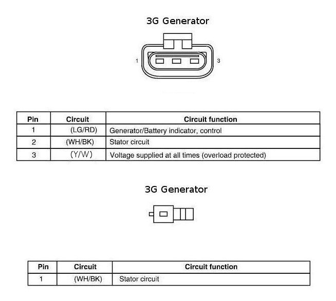
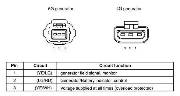
A standard ford 3g alternator plug diagram details the precise pinout of the three-wire stator/regulator connector, typically identified by terminal markings: Stator (S), Field (F), and Voltage Input (I), or alternatively the White/Black, Yellow/White, and Light Green/Red color scheme standard in many North American applications. Reading these schematics requires familiarity with basic Wiring Diagram Basics, where straight lines represent current-carrying conductors and geometric shapes denote specific electrical loads or switches. Technicians must trace each wire to its exact destination to avoid crossing the stator monitor wire with the switched ignition feed.
The White/White with Black stripe wire (Stator or S-terminal) connects directly to the battery positive feed, providing the regulator with an unswitched voltage reference so it can accurately monitor system state of charge. The Yellow/White wire (Field or A-terminal in some variants, or stator tap) drives relay signals or electric choke inputs depending on the specific model year, while the Light Green/Red wire (Indicator or I-terminal) connects to the dashboard battery warning lamp. When the ignition switch turns on, current flows through the dashboard bulb to the I-terminal, grounding the circuit and illuminating the bulb until the alternator begins spinning and generates voltage on the internal diode trio, equalizing the potential and turning the warning light off.
Common Problems and Troubleshooting Methods
Typical faults in this charging architecture include melted connector housings, corroded terminal pins, open circuits in the sense wire, and failed internal voltage regulators that lead to a battery overcharging condition exceeding 15 volts. Diagnosing these issues requires a systematic approach using a digital multimeter set to DC volts and ohms, cross-referencing findings against standard Vehicle Wiring Diagrams for the specific vehicle platform. Technicians should begin by performing a visual inspection of the plastic plug for thermal discoloration, which typically indicates high electrical resistance caused by loose terminal crimps.
Diagnostic testing proceeds with the engine off and the connector unplugged to verify battery voltage at the Stator (S) terminal wire using a chassis ground. Next, the technician measures voltage at the Indicator (I) terminal with the key in the run position to ensure switched power reaches the regulator through the dashboard bulb. If the warning lamp remains illuminated while driving, or if the alternator fails to excite, checking continuity along the small-gauge harness reveals whether a fusible link has opened or a wire has fractured internally due to engine vibration.
Practical Tips and Safety Considerations
Working on high-output automotive charging circuits demands strict adherence to safety protocols, including disconnecting the negative battery cable before servicing any heavy-gauge electrical connections to prevent dangerous short circuits and severe electrical burns. Technicians should always replace damaged plastic regulator plugs with high-temperature ceramic or OEM-grade composite connectors rather than standard vinyl terminals, which melt under sustained underhood thermal loads. Proper wire stripping, crimping with ratcheting tools, and applying dielectric grease help prevent moisture ingress and subsequent copper corrosion.
When modifying charging systems or upgrading to higher-amperage alternators, verifying the ampacity of the main charging cable is critical; undersized wires will overheat and fail catastrophically under maximum load. Regional electrical standards, such as those published by SAE in North America or equivalent bodies in the UK and Australia, provide specific guidelines for wire gauge selection relative to current draw and ambient engine bay temperatures. For complex wiring modifications or persistent electrical faults, consulting an experienced automotive electrician ensures compliance with professional standards and prevents collateral damage to sensitive vehicle control modules.
Conclusion
Mastering the layout and function of the internal regulator connector ensures reliable performance and prevents costly electrical damage during maintenance or custom upgrades. By systematically verifying terminal voltages, maintaining secure connections, and respecting the high-current nature of modern charging circuits, technicians can achieve accurate diagnoses. Proper reference to documentation found in Relay and Component Wiring Diagrams further streamlines the repair process, keeping vehicle electrical systems operating safely and efficiently.
Quick Wiring Specifications & Terminal Guide
| Component / Circuit | Standard Wire Gauge | Recommended Protection |
|---|---|---|
| Control & Trigger Signals | 18 – 20 AWG | 5A – 7.5A Inline Fuse |
| Standard Auxiliary Load | 14 – 16 AWG | 15A – 20A Circuit Breaker |
| Main Power Feed / Supply | 10 – 12 AWG | 30A – 40A Heavy-Duty Relay |
Images References