Introduction
An electric tarp switch wiring diagram 2 way provides the exact schematic blueprint needed to control motorized dump truck and trailer cover systems. Commercial hauling vehicles rely on high-torque DC motors to roll and unroll heavy vinyl tarps over open-top beds, protecting payloads from weather and road debris. Mastering this specific configuration prevents motor burnout, eliminates intermittent electrical faults, and ensures reliable daily operation on the road. Whether retrofitting an older manual crank mechanism or servicing a factory-installed automated assembly, proper circuit planning remains essential for heavy-duty automotive electrical work.
💡 Technical Key Takeaways:
- Core Focus: Diagnostic schematic and terminal connection layout for Electric Tarp Switch Wiring Diagram 2 Way.
- Target Scope: Field technicians, automotive DIYers, and residential/commercial electricians.
- Safety Rule: Always disconnect the primary power source/battery terminal and verify zero voltage with a multimeter before touching wires.
Core Concepts and Wiring Fundamentals
Heavy-duty vehicle electrical architecture operates primarily on 12V or 24V direct current (DC) supplied directly from the chassis batteries through high-amperage cabling. The electric tarp system utilizes a specialized momentary-contact, double-pole, double-throw (DPDT) center-off switch configured for polarity reversal. Polarity reversal allows the direct current motor to spin clockwise to cover the load and counter-clockwise to uncover the bed without requiring complex mechanical gearboxes. Because these motors draw substantial operating current, often exceeding forty amperes under load, direct switching without intermediate control relays can melt switch contacts and degrade insulation over time.
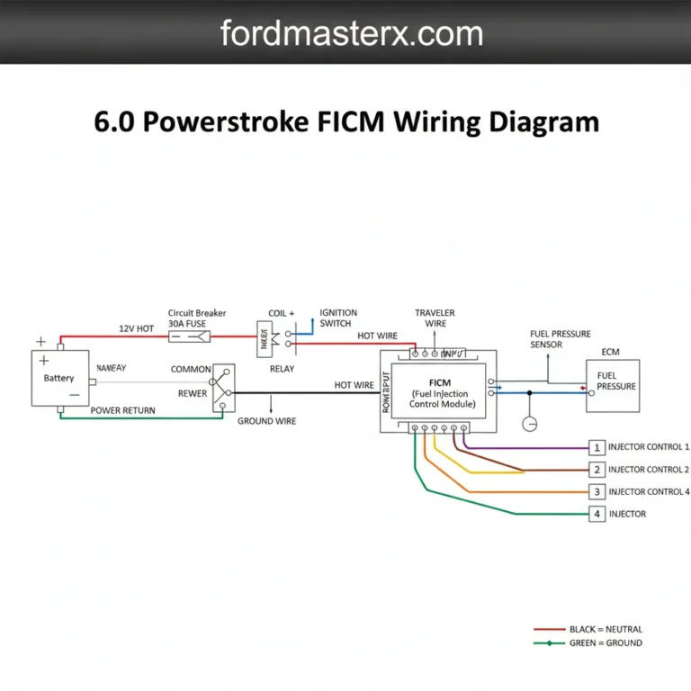
To protect the control circuit and manage high current safely, professional technicians frequently pair the switch with dual high-current automotive relays or rely on robust tarp switches rated specifically for continuous high-amperage duty. A dedicated manual-reset circuit breaker or high-amp inline fuse positioned within inches of the main battery power source protects the entire feeder harness against short circuits caused by vibration or chafing against the steel chassis frame. Grounding must always be verified directly to bare, unpainted metal on the vehicle frame or returned through a dedicated heavy-gauge negative conductor.
[Vehicle electrical system failures, including overloaded tarp motor circuits, represent a significant percentage of commercial truck electrical service calls documented in industry maintenance records.] — Society of Automotive Engineers (SAE)
Diagram Explanation and Key Components
Reading an electric tarp switch wiring diagram 2 way requires understanding standardized automotive schematic symbols, wire color conventions, and terminal designations. DPDT center-off switches typically feature six active terminals: two incoming power and ground feeds (or cross-jumped polarity jumpers), two switched output leads running to the motor, and internal bridging contacts that disconnect the circuit completely when the rocker returns to the neutral spring-loaded position. Cross-jumper wires connecting opposite corners of the switch terminals create the necessary polarity reversal loop when the toggle is pressed forward or backward.
Regional standards dictate specific wire insulation colors and sizing practices across global jurisdictions. In North America, conforming to guidelines established by organizations like the SAE, primary power feeds are typically red or orange, while ground lines are black or dark green. In the United Kingdom and Australia, automotive wiring practices often align with BS standards or local transport regulations where brown might designate live feeds and black or yellow-green designates earth paths. Reviewing detailed schematics available in Vehicle Wiring Diagrams helps clarify these terminal layouts before cutting any copper.
Common Problems and Troubleshooting Methods
Systematic diagnostic procedures begin with visual inspections of physical wear points, including hinge pivot areas and where wiring harnesses pass through the truck chassis to the trailer. A typical field failure involves a blown inline fuse or tripped thermal breaker caused by a stalled motor binding against a frozen or overloaded tarp roll. Technicians must utilize a digital multimeter set to DC voltage to verify that battery voltage reaches the input side of the switch, and subsequently check whether voltage successfully reverses polarity across the output motor leads when the switch is actuated.
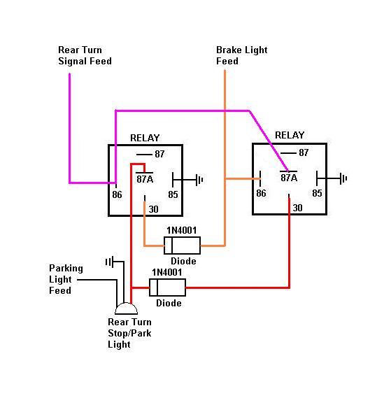
Corrosion inside weatherproof switch housings represents another frequent culprit, creating high-resistance connections that generate excessive heat and drop operating voltage below what the motor requires to turn. If the switch clicks but the motor remains stationary, the fault often points toward a failing internal contact bridge within the switch or a compromised ground connection at the motor mounting plate. For complex control setups utilizing auxiliary switching boxes, referencing resources found in Relay and Component Wiring Diagrams assists in isolating whether the issue lies in the low-current control leg or the high-current power delivery path.
Practical Tips and Safety Considerations
Working on high-amperage vehicle electrical systems demands strict adherence to safety protocols to prevent severe burns, component damage, or accidental electrical fires. Always disconnect the primary battery negative terminal before cutting, stripping, or terminating any heavy-gauge power conductors in the harness. Utilizing marine-grade, tin-coated copper wire and heat-shrink crimp terminals prevents moisture intrusion and galvanic corrosion, which is especially critical for commercial vehicles operating in wet road conditions or winter salt environments.
Wire gauge selection must match the current draw and total circuit length; running undersized wire over a long chassis span causes excessive voltage drop, sluggish motor operation, and dangerous overheating of the insulation jacket. Secure all wiring harness runs securely using industrial nylon zip ties and rubber grommets wherever harnesses pass through sheet metal cutouts to prevent chafing from constant vehicle vibration. For home workshop installations or auxiliary equipment setups, reviewing principles outlined in Appliance and Device Wiring provides additional foundational insights into safe circuit construction.
Conclusion
Installing and servicing automated tarp mechanisms requires careful attention to current ratings, polarity reversal logic, and robust mechanical protection of all circuit paths. By following standardized schematics, utilizing properly sized copper conductors, and performing methodical voltage drops tests during diagnosis, technicians ensure long-term reliability under demanding commercial operating conditions. Diligent adherence to these electrical fundamentals prevents costly roadside breakdowns and maintains safe operation across every fleet vehicle.
Quick Wiring Specifications & Terminal Guide
| Component / Circuit | Standard Wire Gauge | Recommended Protection |
|---|---|---|
| Control & Trigger Signals | 18 – 20 AWG | 5A – 7.5A Inline Fuse |
| Standard Auxiliary Load | 14 – 16 AWG | 15A – 20A Circuit Breaker |
| Main Power Feed / Supply | 10 – 12 AWG | 30A – 40A Heavy-Duty Relay |
Images References