Introduction
An electric diagram for wiring recessed lights serves as the definitive roadmap for planning, installing, and maintaining downward-facing ceiling illumination fixtures. Proper comprehension of these schematics ensures that multiple lighting fixtures distribute loads evenly across branch circuits while preventing dangerous overloads. These diagrams find extensive application in residential renovations, commercial office retrofits, and new construction projects where clean ceiling aesthetics and uniform task lighting are required. Mastering these layouts improves safety, guarantees compliance with regional building standards, and drastically reduces troubleshooting time when lighting circuits fail to operate correctly.
💡 Technical Key Takeaways:
- Core Focus: Diagnostic schematic and terminal connection layout for Electric Diagram For Wiring Recessed Lights.
- Target Scope: Field technicians, automotive DIYers, and residential/commercial electricians.
- Safety Rule: Always disconnect the primary power source/battery terminal and verify zero voltage with a multimeter before touching wires.
Core Concepts and Wiring Fundamentals
Recessed lighting systems operate on standard household mains voltage, transmitting electrical current from a primary service panel through wall switches directly to the fixtures. A complete household circuit incorporates three primary conductors: a live or hot wire delivering current, a neutral wire completing the return path, and a protective earth ground wire that prevents shock hazards. These conductors terminate inside individual junction boxes attached to each light housing, utilizing push-in wire connectors or traditional twist-on wire nuts to maintain secure mechanical and electrical contact.
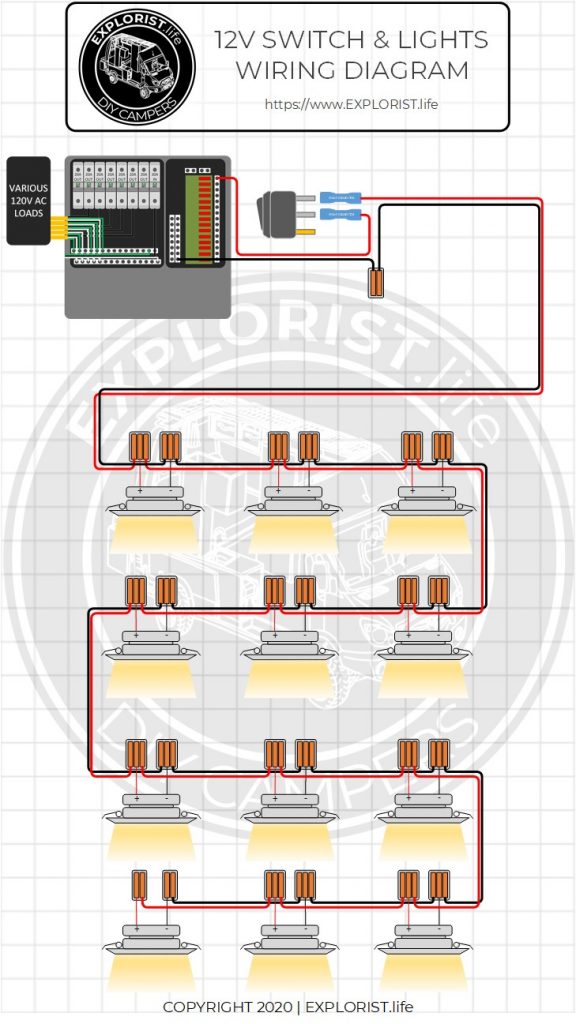
Daisy-chaining represents the standard method for linking multiple downlights on a single switch leg. In this configuration, power enters the first fixture’s junction box, feeds the internal lamp socket, and continues onward to supply the next fixture in the sequence. Switches are wired in series with the hot conductor, breaking the circuit upstream to control power delivery while leaving the neutral and ground paths continuous throughout the run.
Regional standards dictate wire color codes and installation requirements across different global jurisdictions. Under the National Electrical Code (NEC/NFPA 70) in the United States and the Canadian Electrical Code (CEC), hot wires are typically black or red, neutral wires are white, and ground wires are bare copper or green. Conversely, the United Kingdom (BS 7671) and Australia/New Zealand (AS/NZS 3000) utilize brown for live, blue for neutral, and green-and-yellow for earth. Installers must always consult local regulations to verify acceptable conductor sizing and ampacity limits.
Electrical fires and shocks remain a significant risk in residential properties, making adherence to strict installation codes and proper circuit loading essential for safety — Electrical Safety Foundation International (ESFI)
Diagram Explanation and Key Components
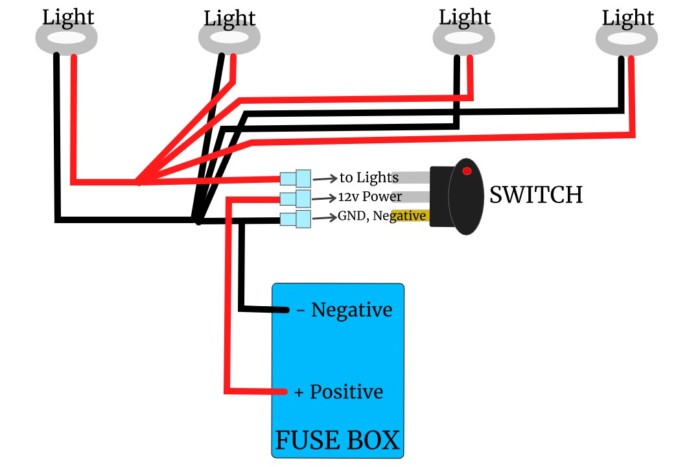
An electric diagram for wiring recessed lights translates physical hardware into standardized schematic symbols, using solid lines for active conductors, dashed lines for switch legs, and specific geometric icons to represent junction boxes, thermal protectors, and lamp holders. Reading these blueprints requires identifying the power source originating from a circuit breaker, following the line to a wall-mounted single-pole or three-way switch, and tracing the subsequent pathways to each individual light fixture. Line types distinguish permanent feeds from switched legs, while numerical annotations often denote minimum wire gauges required for the total connected load.
Modern recessed installations frequently incorporate integrated LED modules or separate housings containing standard lamp sockets. Insulation Contact (IC)-rated housings appear prominently in schematics designed for residential ceilings insulated with fiberglass or cellulose, as these units can safely touch thermal insulation without creating a fire hazard. Non-IC rated housings require a mandatory minimum clearance from insulation, a critical detail that must be cross-referenced between the wiring diagram and physical installation site.
Further insights into home installation layouts and supporting hardware can be found by reviewing Home Electrical Wiring Diagrams. Technicians should also study Wiring Diagram Basics to understand standard drafting conventions, line weights, and universal electrical symbols before attempting complex multi-room lighting layouts.
Common Problems and Troubleshooting Methods
Systematic fault-finding begins by confirming that the mains supply is completely de-energized before opening any fixture junction box or switch plate. Typical failures in recessed lighting circuits include intermittent flickering, dead fixtures downstream in a daisy-chain, or thermal limiters tripping repeatedly due to enclosed overheating. When a single light fails while others remain functional, the issue is usually localized to a loose wire nut inside that specific fixture’s junction box or a burned-out lamp module. If an entire run of lights goes dark simultaneously, the fault typically resides upstream at the wall switch or the preceding junction box connection.
Diagnostic procedures require a digital multimeter configured for voltage and continuity testing. Technicians should verify input voltage at the switch terminals, check for continuity along the neutral return path, and inspect ground continuity to ensure all metal housings are safely bonded. Thermal cycling often shakes loose push-in wire connectors, making physical tug tests and visual inspections mandatory during any diagnostic workflow. For broader testing methodologies applicable to residential and commercial systems, consult the resources available under Wiring Troubleshooting.
Practical Tips and Safety Considerations
Working with mains-voltage lighting systems demands absolute adherence to safety protocols, starting with turning off the circuit breaker and verifying zero energy potential using a reliable non-contact voltage tester or multimeter. Never rely solely on wall switch positions when servicing ceiling fixtures, as miswired switches can leave hot conductors live inside the junction box. Installers must also calculate the total wattage load of all LED or incandescent lamps combined on a single circuit to prevent tripping thermal overloads or exceeding the maximum breaker rating.
A common real-world mistake involves crowding too many conductors into small junction boxes, which violates fill capacity rules and pinches wire insulation, leading to short circuits over time. Always secure cables with appropriate clamps where they enter metal or plastic enclosures to prevent strain on the internal wire nuts. Local building codes mandate that all electrical connections remain accessible for future inspection, meaning junction boxes must never be permanently buried behind drywall or inaccessible ceiling finishes.
Conclusion
Mastering an electric diagram for wiring recessed lights bridges the gap between theoretical electrical design and safe, compliant physical installations. Careful attention to circuit loading, correct identification of live, neutral, and ground conductors, and rigorous adherence to regional codes safeguard both property and occupants. Whether planning a new layout or diagnosing a failing lighting run, systematic adherence to schematics ensures long-term operational reliability. For further exploration of related electrical systems, review specialized guides such as Relay and Component Wiring Diagrams.
Quick Wiring Specifications & Terminal Guide
| Component / Circuit | Standard Wire Gauge | Recommended Protection |
|---|---|---|
| Control & Trigger Signals | 18 – 20 AWG | 5A – 7.5A Inline Fuse |
| Standard Auxiliary Load | 14 – 16 AWG | 15A – 20A Circuit Breaker |
| Main Power Feed / Supply | 10 – 12 AWG | 30A – 40A Heavy-Duty Relay |
Images References