Introduction
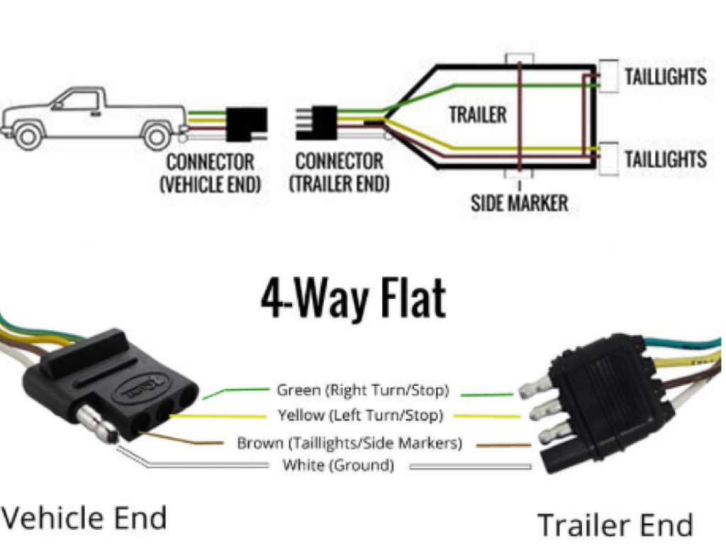
A diagram 4 pin flat outlines the standard low-voltage electrical connection utilized primarily for light-duty towing applications to transmit essential lighting signals from a towing vehicle to a trailer. This specific connector configuration standardizes the transmission of running lights, left turn signals, right turn signals, and ground continuity across a molded rubber or plastic plug housing. Understanding how to interpret this schematic layout directly improves installation safety, prevents lighting failures on public roadways, and ensures accurate troubleshooting when electrical faults occur. Mastering these schematics is essential for anyone working with Vehicle Wiring Diagrams to maintain compliance with automotive lighting regulations across North America, the United Kingdom, and Australia.
💡 Technical Key Takeaways:
- Core Focus: Diagnostic schematic and terminal connection layout for Diagram 4 Pin Flat.
- Target Scope: Field technicians, automotive DIYers, and residential/commercial electricians.
- Safety Rule: Always disconnect the primary power source/battery terminal and verify zero voltage with a multimeter before touching wires.
Core Concepts and Wiring Fundamentals
The 4-pin flat connector operates on a 12-volt or 24-volt direct current (DC) automotive electrical system, relying on dedicated circuits protected by vehicle fuses to power auxiliary trailer lamps. Power originates at the towing vehicle’s lighting control module or tail lamp harness, where switches and relays route electrical current to specific circuits based on driver inputs. The physical connector consists of a molded female socket on the vehicle side and a matching male plug on the trailer harness, each containing four distinct conductive brass pins or receptacles designed for a secure mechanical and electrical fit.
Ground continuity remains the foundational element of this circuit architecture, as an unstable ground path causes intermittent lighting faults and erratic behavior such as glowing dashboard indicators or dim running lamps. The system utilizes a shared ground wire that must connect cleanly to the bare metal frame of both the towing vehicle and the towed apparatus. Voltage supply flows through copper conductors sized appropriately for lighting loads, typically utilizing standard automotive wire gauges governed by practices recommended by the Society of Automotive Engineers (SAE) or equivalent regional standards.
Corrosion and high-resistance connections account for a vast majority of lighting failures in auxiliary towing harnesses according to vehicle safety maintenance reports — SAE International
Diagram Explanation and Key Components
Reading a diagram 4 pin flat requires recognizing standardized wire color codes and pin placement configurations that remain consistent across most light-duty utility and recreational trailers. The layout typically follows a sequential order starting with the exposed male pin or the protected female terminal, aligning specific functions to designated wire colors. In standard practices across North America, the white wire connects to the ground terminal, the brown wire controls the tail, marker, and license plate lights, the yellow wire manages the left turn signal and left brake light, and the green wire operates the right turn signal and right brake light.
Schematics illustrate these connections using single-line diagrams or exploded harness views, marking splice points, fuse block locations, and ground lug attachments. Technicians must note that international wiring standards may vary regarding jacket colors, meaning verification with a digital multimeter is always required before final assembly. Understanding Wiring Diagram Basics helps beginners decode line types, abbreviations, and terminal designations found in comprehensive factory service manuals.
Common Problems and Troubleshooting Methods
Systematic diagnostic procedures for a diagram 4 pin flat involve isolating faults between the towing vehicle supply side and the towed equipment receiver harness using structured electrical testing techniques. Typical failures include blown vehicle fuses caused by pinched wires, high resistance at oxidized brass terminals, open circuits from fatigue fractures, and compromised ground connections resulting from road salt and moisture exposure. Technicians approach these symptoms by first disconnecting the harness and inspecting the physical pins for green corrosion, debris, or mechanical distortion.
Diagnostic workflows utilize a digital multimeter set to DC voltage or a specialized circuit tester to verify that 12 volts reach the respective pins when the vehicle headlamps, brakes, and turn signals are active. If vehicle output checks normal but trailer lamps fail to illuminate, the fault lies downstream within the trailer sub-harness or at the individual lamp ground eyelets. Mechanics should reference Wiring Troubleshooting guides to execute systematic voltage drop tests and continuity checks without damaging sensitive vehicle body control modules.
Practical Tips and Safety Considerations
Executing clean installations and reliable repairs requires adhering to strict mechanical protection standards, including applying dielectric grease to inhibit corrosion and securing loose wires away from moving suspension components or hot exhaust pipes. Working on vehicle electrical systems demands caution; always disconnect the negative battery terminal before cutting into factory harnesses or tapping into high-current power feeds to prevent accidental short circuits or module damage. Installers must use heat-shrink butt connectors or soldered joints sealed with adhesive-lined tubing to shield copper strands from environmental moisture.
Wire gauge selection must match or exceed the original equipment manufacturer specifications to prevent excessive voltage drop over extended harness lengths. Regional regulations, such as the National Electrical Code for stationary systems or applicable national road transport rules for mobile setups, mandate proper circuit protection via appropriately rated fuses. When complex electrical modifications intersect with multiplexed vehicle lighting networks, consulting a qualified automotive technician ensures that auxiliary loads do not overload factory lighting control units.
Conclusion
Mastering the schematic layout and physical operation of auxiliary trailer lighting connectors guarantees safe towing operations and efficient electrical fault isolation. Proper interpretation of wire functions, diligent maintenance of terminal cleanliness, and adherence to systematic diagnostic procedures eliminate common roadside lighting failures. Reviewing resources covering Relay and Component Wiring Diagrams provides further insight into managing heavier electrical loads safely. Diligent attention to detail during installation and repair safeguards both equipment longevity and highway safety.
Quick Wiring Specifications & Terminal Guide
| Component / Circuit | Standard Wire Gauge | Recommended Protection |
|---|---|---|
| Control & Trigger Signals | 18 – 20 AWG | 5A – 7.5A Inline Fuse |
| Standard Auxiliary Load | 14 – 16 AWG | 15A – 20A Circuit Breaker |
| Main Power Feed / Supply | 10 – 12 AWG | 30A – 40A Heavy-Duty Relay |
Images References