Introduction
The alternator exciter circuit is a low-current electrical pathway responsible for initializing the magnetic field inside an automotive alternator so that power generation can begin. Without this initial electrical feed, the rotor fails to magnetize, leaving the charging system completely dormant even when the engine runs at high speeds. This specific control loop bridges the gap between the dashboard warning indicator, the ignition switch, and the internal voltage regulator. Grasping the operation of this circuit helps technicians differentiate between a failed generating unit and a simple wiring fault in auxiliary control harnesses. Mastering this pathway supports accurate Wiring Troubleshooting across modern and vintage 12-volt vehicle platforms found in North America, the UK, Europe, and Australasia.
💡 Technical Key Takeaways:
- Core Focus: Diagnostic schematic and terminal connection layout for Alternator Exciter Circuit.
- Target Scope: Field technicians, automotive DIYers, and residential/commercial electricians.
- Safety Rule: Always disconnect the primary power source/battery terminal and verify zero voltage with a multimeter before touching wires.
Core Concepts and Wiring Fundamentals
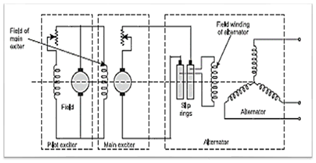
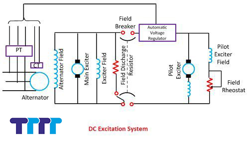
An alternator exciter circuit functions by supplying a controlled, low-amperage voltage signal to the rotor winding when the ignition key turns to the run position. This initial current establishes a baseline magnetic field, which induces alternating current in the stator coils as the engine rotates the pulley. Once the internal diodes rectify this current into direct current, part of the generated output feeds back into the rotor, creating a self-sustaining loop known as self-excitation.
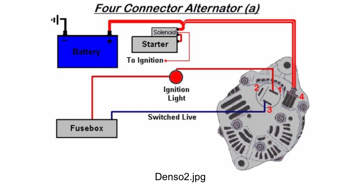
Wiring configurations for this circuit vary depending on the vehicle manufacturer and the age of the charging system. Older internal-regulator units typically utilize a single excitation wire running from the dashboard charge lamp directly to terminal L on the rear of the alternator. Modern computer-controlled powertrains route the exciter circuit through the engine control module, utilizing pulse-width modulation signals to govern alternator output dynamically based on electrical load demands.
Fuses, fusible links, and dedicated relays protect these sensitive control wires from excessive current draw and short circuits. In many passenger vehicles, a blown instrument cluster fuse disables the charge indicator bulb, inadvertently breaking the exciter path and preventing the alternator from waking up upon startup. Mechanics must verify power delivery at the exciter terminal before condemning an expensive alternator assembly.
[Finding] — Society of Automotive Engineers (SAE) standards dictate that low-voltage automotive control circuits must maintain low resistance thresholds to prevent voltage drop from disrupting critical ECU communications and generator excitation.
Diagram Explanation and Key Components
Reading a schematic for an alternator exciter circuit requires identifying standard automotive symbols, including the ignition switch, indicator lamp, resistor wires, and multi-pin regulator connectors. On a typical Vehicle Wiring Diagrams layout, the exciter wire is often labeled with standard terminal designations such as IGN, L, or DF, depending on whether the system uses a GM, Ford, Chrysler, or imported configuration.
Color coding for these wires changes significantly across regional markets and manufacturing eras. North American vehicles frequently use brown with a white stripe for charge indicator circuits, while European models adhering to DIN standards utilize specific blue or blue-white color assignments for alternator excitation. Technicians must always consult manufacturer-specific documentation rather than relying purely on visual wire color matching.
The primary components within this schematic loop include the battery supply, the ignition switch contacts, the dashboard warning bulb or electronic driver circuit, and the internal voltage regulator brushes. Tracing the line from the positive battery post through the fuse panel to the exciter terminal clarifies how system voltage reaches the rotor windings prior to engine cranking.
Common Problems and Troubleshooting Methods
Diagnostic procedures for an alternator exciter circuit involve a systematic approach using a digital multimeter to isolate high resistance, open circuits, and grounded control lines. Common symptoms include a persistent battery warning light on the dashboard, a dead battery following a short drive, or an alternator that fails to charge until the engine is revved past a specific RPM threshold. Technicians should always disconnect the negative battery cable before servicing high-current connections to prevent accidental arcing.
Begin the diagnostic process by verifying battery state of charge and checking all relevant fuses in the under-hood and cabin fuse blocks. Turn the ignition key to the run position without starting the engine, and test for voltage at the exciter wire terminal disconnected from the alternator. A reading significantly lower than battery voltage indicates excessive resistance in the ignition switch, corroded harness connectors, or a burned-out dashboard indicator bulb.
If voltage is present at the exciter wire, reconnect the harness and perform a voltage drop test while the ignition is on. Excessive voltage drop across the exciter wire points to internal strand corrosion or a damaged crimp terminal within the wiring loom. Mechanics frequently encounter oil contamination inside connector housings near the front of the engine block, which introduces high resistance and disrupts the delicate excitation signal.
Practical Tips and Safety Considerations
Working on vehicle electrical systems demands strict adherence to safety protocols, particularly when handling heavy-gauge cables connected directly to the battery positive post. Always disconnect the negative battery terminal before repairing or replacing alternator wiring harnesses to prevent personal injury and prevent damage to sensitive electronic control units. Use proper terminal crimping tools and heat-shrink tubing with adhesive lining to seal repaired exciter wires against moisture and road salt ingress.
A common mistake during alternator replacement is reusing a heavily corroded exciter plug or forcing a mismatched connector housing onto the regulator pins. This practice leads to intermittent charging faults that mimic a defective alternator. Ensure all wiring harness retaining clips are secured away from moving engine belts and hot exhaust manifolds to prevent chafing and subsequent short circuits.
Conclusion
Understanding the alternator exciter circuit empowers technicians and DIY mechanics to resolve complex charging system failures quickly and accurately. By methodically testing voltage levels, checking indicator lamp circuits, and inspecting harness integrity, professionals avoid unnecessary parts replacement. Reviewing proper schematics and adhering to safe disconnection practices ensures long-term electrical reliability. For further guidance on related electrical layouts, consult comprehensive resources on Relay and Component Wiring Diagrams.
Quick Wiring Specifications & Terminal Guide
| Component / Circuit | Standard Wire Gauge | Recommended Protection |
|---|---|---|
| Control & Trigger Signals | 18 – 20 AWG | 5A – 7.5A Inline Fuse |
| Standard Auxiliary Load | 14 – 16 AWG | 15A – 20A Circuit Breaker |
| Main Power Feed / Supply | 10 – 12 AWG | 30A – 40A Heavy-Duty Relay |
Images References