Introduction
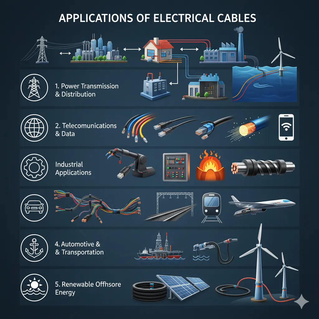
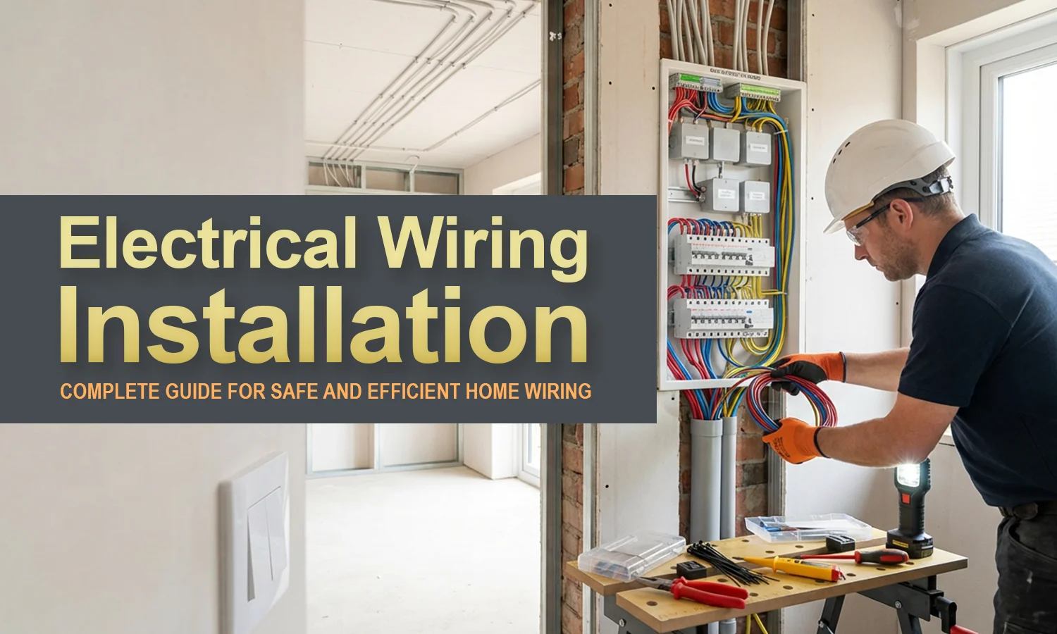
Electrical wiring application encompasses the systematic installation, routing, and connection of conductors across residential structures and 12V/24V automotive platforms to safely distribute electrical power and signals. According to SAE J1128 automotive wiring standards, low-tension primary cable insulations must maintain specific thermal and mechanical ratings to prevent short circuits under severe engine bay conditions. Executing these installations demands strict adherence to engineering schematics, precise wire sizing, and rigorous voltage drop calculations. Professionals and experienced hobbyists rely on clear documentation, such as those found across Wiring Diagram Basics, to ensure circuits operate within safe current limits. Neglecting proper application protocols introduces catastrophic hazards, including thermal overload, insulation breakdown, and component failure.
Wiring Technical Snapshot:
- Core Focus: Safe and systematic installation of electrical power and signal pathways.
- Target Scope: 12V/24V automotive circuits, heavy machinery, and residential electrical networks.
- Key Recommendation: Always verify conductor ampacity against circuit load limits before final energization.
Core Principles and Detailed Overview
Successful electrical wiring application relies on mastering circuit fundamentals, Ohm’s Law, and accurate schematic interpretation to prevent excessive resistance and thermal runaway. Every circuit requires an uninterrupted power source, a controlled load, and a low-resistance return path back to the power supply negative terminal or earth ground. In modern vehicle architectures, understanding complex multiplexed networks requires referencing specialized Vehicle Wiring Diagrams to trace power distribution accurately without damaging delicate control modules. Technicians must utilize digital multimeters to verify continuity, check voltage drops under load, and isolate high-resistance connections before declaring a system operationally sound.
Key Specifications and Breakdown
| Circuit / Terminal | Standard Wire Color / Gauge | Operational Role & Safety Check |
|---|---|---|
| 12V Battery Positive Feed | Red / 10 AWG to 4 AWG | Transfers unswitched high current from battery; verified via zero-voltage drop test. |
| Chassis Ground Return | Black / 12 AWG to 8 AWG | Completes the low-voltage loop; verified with a resistance measurement under 0.1 ohms. |
| Residential Branch Circuit Hot | Black or Red / 14 AWG to 12 AWG | Carries 120V AC utility power; verified with a calibrated non-contact voltage tester. |
Electrical installations must strictly adhere to established safety codes and continuous load limitations to mitigate structural fire risks and arc faults. — National Fire Protection Association (NFPA)
Step-by-Step Practical Application and Guidelines
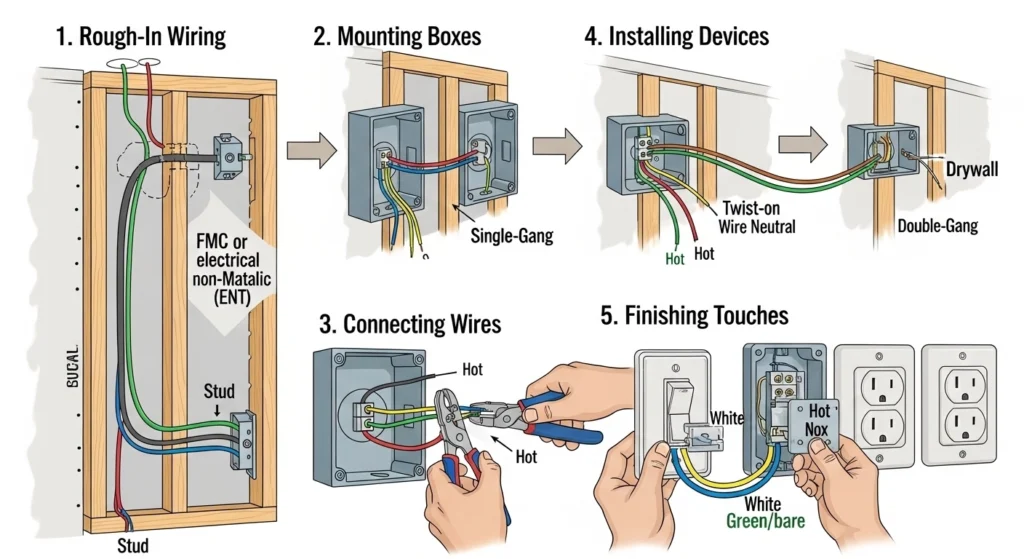
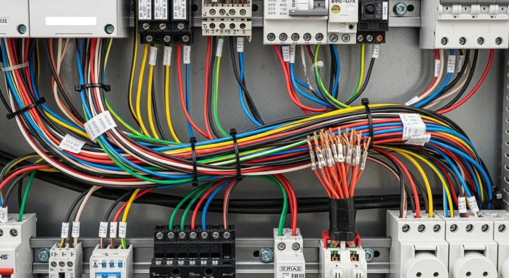
Executing an electrical wiring application requires a methodical process starting with comprehensive circuit mapping and load analysis. Begin by disconnecting the primary power source or vehicle battery to eliminate shock hazards during physical installation. Select appropriate American Wire Gauge (AWG) conductors based on total circuit amperage and maximum permissible run length. Route wire harnesses away from sharp metallic edges, extreme exhaust heat sources, and moving mechanical linkages, securing every span with insulated P-clamps or nylon zip ties. Terminate connections using ratchet-crimping tools and heat-shrink tubing featuring integrated adhesive liners to seal out moisture and prevent environmental corrosion. Finally, re-energize the circuit incrementally, using a fused jumper wire or a digital multimeter current clamp to confirm operational parameters before final deployment.
Common Challenges and How to Avoid Them
Voltage drop caused by undersized conductors, loose crimps, and oxidized ground points represents the most frequent failure point in complex electrical systems. Mechanics often misdiagnose intermittent sensor faults when the actual root cause stems from high-resistance chassis grounds or damaged wiring harnesses routed near high-electromagnetic-interference sources. Utilizing improper gauge wire for high-draw accessories will cause thermal degradation of the insulation over time. Reference organized documentation like Wiring Troubleshooting to systematically isolate fault zones, verify sensor reference voltages, and restore low-resistance pathways efficiently.
💬 Frequently Asked Questions
Explore More Wiring Diagrams and Schematics on ReadWires
Mastering electrical wiring application demands continuous access to accurate, manufacturer-grade documentation, schematics, and diagnostic guides. Practitioners can expand their technical expertise by browsing the extensive reference library hosted directly at ReadWires.com, where detailed schematics empower precise installations across every domain.
Wiring Diagram Schematics & Details