Introduction
Diagnosing a 1956 chevy ignition system involves systematically evaluating a vintage 12-volt direct current electrical circuit to identify voltage drops, component failures, or high-resistance paths. This process matters because classic automotive platforms rely on mechanical points, oil-filled coils, and fabric-braided wiring that degrade over decades of thermal cycling and vibration. Such troubleshooting procedures are applied inside restoration shops, roadside garages, and home workshops across North America, the UK, and Australia to restore reliable spark delivery. Understanding this workflow improves diagnostic accuracy, prevents unnecessary component replacement, and ensures safe operation of historical vehicles.
💡 Technical Key Takeaways:
- Core Focus: Diagnostic schematic and terminal connection layout for Diagnosing A 1956 Chevy Ignition System.
- Target Scope: Field technicians, automotive DIYers, and residential/commercial electricians.
- Safety Rule: Always disconnect the primary power source/battery terminal and verify zero voltage with a multimeter before touching wires.
Core Concepts and Wiring Fundamentals
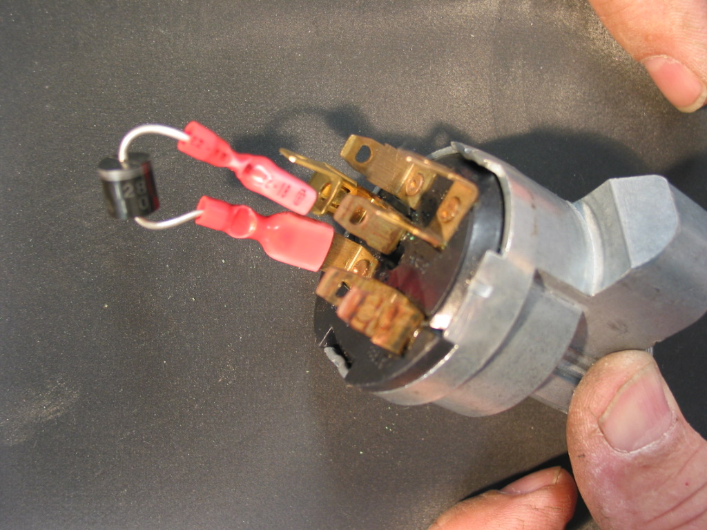
The standard 1956 Chevrolet ignition circuit operates on a simple 12-volt, negative-ground architecture governed by automotive standards set by organizations like SAE International. Power originates at the battery, flows through the ignition switch located on the dashboard, and travels via cloth-wrapped or plastic-insulated primary wires to the positive terminal of the ignition coil.
Vehicle Wiring Diagrams provide the roadmap for tracing this current path from the power source through the bulkhead connector to the engine bay.
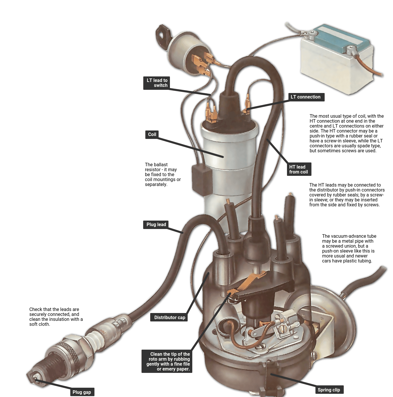
Inside the cylindrical ignition coil, primary low-voltage current creates a magnetic field around a secondary winding. When the engine rotates, a mechanical camshaft lobe opens the ignition points inside the distributor, instantly collapsing that magnetic field. This sudden collapse induces high voltage—often exceeding 20,000 volts—which travels through the central coil wire and distributor cap to fire the spark plugs in the correct firing order.
Maintaining clean physical connections and low-resistance grounds is critical in these older circuits. Corrosion at the battery terminals, loose bulkhead connectors, or high resistance at the ignition switch can starve the coil of primary voltage, resulting in a weak spark or a complete no-start condition. Technicians must verify that current flows uninterrupted through every link in the chain before condemning expensive ignition parts.
[Finding] — According to historical automotive electrical studies by SAE International, high-resistance connections in primary ignition circuits account for a significant percentage of intermittent classic car no-start conditions.
Diagram Explanation and Key Components
Reading vintage automotive schematics requires familiarity with simplified graphical symbols representing physical hardware like ignition switches, ballast resistors, and breaker points.
Wiring Diagram Basics help technicians decode line types, color codes, and component callouts unique to mid-1950s General Motors documentation.
The primary circuit includes the ignition switch, primary coil winding, and breaker points. The secondary circuit encompasses the coil secondary winding, high-tension coil wire, distributor cap, rotor, spark plug wires, and spark plugs.
Factory diagrams utilize solid lines to represent unswitched power feeds and dashed lines for switched ignition circuits. Color coding on original harnesses typically features solid colors with tracer stripes, though faded insulation on survivor vehicles often obscures these markers.
Every component plays a specific role. The ignition switch routes battery voltage to the coil. The ballast resistor, often integrated into the wiring harness or coil feed on later 12V conversions, drops operating voltage to the coil during normal running to extend point life. The condenser absorbs electrical energy when the points open, preventing destructive arcing across the contact surfaces.
Common Problems and Troubleshooting Methods
Typical faults in a vintage ignition setup include pitted breaker points, shorted condensers, cracked distributor caps, and degraded copper-core spark plug wires.
Wiring Troubleshooting methodologies dictate a logical, step-by-step diagnostic path rather than random part swapping.
Start by verifying primary voltage at the positive coil terminal with the ignition switch in the run position. If zero volts register, trace backward through the ignition switch and fuse block using a digital multimeter or test light. If voltage is present at the coil positive terminal, check for voltage fluctuation at the negative coil terminal while manually opening and closing the breaker points.
An absence of switching voltage indicates closed points, burned contacts, or a grounded condenser. Technicians must always disconnect the vehicle battery before performing continuity checks or resistance measurements on isolated wiring harnesses to prevent meter damage or accidental shorts.
Practical Tips and Safety Considerations
Safety remains paramount when working around high-voltage secondary ignition circuits capable of delivering a painful or hazardous electrical shock. Technicians should always disconnect the negative battery cable before servicing under-hood wiring, and never touch the coil wire or spark plug terminals while the engine is cranking or running.
When repairing damaged wiring, select stranded copper wire matched to the original gauge specifications and utilize proper soldering or crimping techniques coupled with heat-shrink tubing to protect against under-hood moisture and oil.
A common mistake involves ignoring the condition of the engine block ground strap; without a solid ground path between the engine and the chassis, primary ignition current cannot complete its loop back to the battery. Always verify that all mechanical mounting surfaces are free of paint, rust, and grease.
Conclusion
Systematic diagnostic procedures take the guesswork out of restoring and maintaining vintage vehicle electrical systems. By understanding circuit fundamentals, accurately interpreting factory schematics, and executing methodical voltage and resistance tests, mechanics can quickly isolate faults in classic setups. Adhering to proper safety precautions and using quality repair materials ensures long-term reliability on the road. Further exploration of related automotive circuits can be found through reviewing comprehensive Relay and Component Wiring Diagrams.
Quick Wiring Specifications & Terminal Guide
| Component / Circuit | Standard Wire Gauge | Recommended Protection |
|---|---|---|
| Control & Trigger Signals | 18 – 20 AWG | 5A – 7.5A Inline Fuse |
| Standard Auxiliary Load | 14 – 16 AWG | 15A – 20A Circuit Breaker |
| Main Power Feed / Supply | 10 – 12 AWG | 30A – 40A Heavy-Duty Relay |
Images References