Introduction
Wiring diagram decoding is the systematic process of interpreting graphical representations of electrical circuits, symbols, and terminal identifications to understand how power flows through a system. Mastering this skill matters because guesswork leads to blown fuses, damaged control modules, and safety hazards whether working on automotive networks, industrial machinery, or residential grids. Understanding these schematics directly improves troubleshooting accuracy, reduces diagnostic time, and ensures that installations meet established engineering standards.
💡 Technical Key Takeaways:
- Core Focus: Diagnostic schematic and terminal connection layout for Wiring Diagram Decoding.
- Target Scope: Field technicians, automotive DIYers, and residential/commercial electricians.
- Safety Rule: Always disconnect the primary power source/battery terminal and verify zero voltage with a multimeter before touching wires.
Core Concepts and Wiring Fundamentals
Every electrical circuit relies on a complete loop consisting of a power source, a load, conductors, and a return path to ground. Power sources supply the necessary voltage, such as 12V direct current in Vehicle Wiring Diagrams or mains voltage alternating current in residential properties. Conductors, commonly copper wire, transport this electrical energy across long distances while maintaining acceptable resistance levels. Fuses and circuit breakers act as vital protective devices designed to interrupt current flow automatically when excessive amperage occurs due to an overload or short circuit.
Relays and switches control the delivery of power without requiring heavy-gauge wiring to run directly through dashboard switches or sensitive microprocessors. A switch manually opens or closes a circuit, whereas an electromagnetic relay uses a low-current control circuit to switch a high-current load. Ground connections complete the circuit path back to the power source chassis or earth. A compromised ground point introduces high resistance, creating mysterious voltage drops that disable entire electrical subsystems despite an intact power feed.
Electrical faults involving high-resistance ground connections account for a significant percentage of intermittent electrical failures in complex diagnostic scenarios — National Fire Protection Association (NFPA)
Diagram Explanation and Key Components
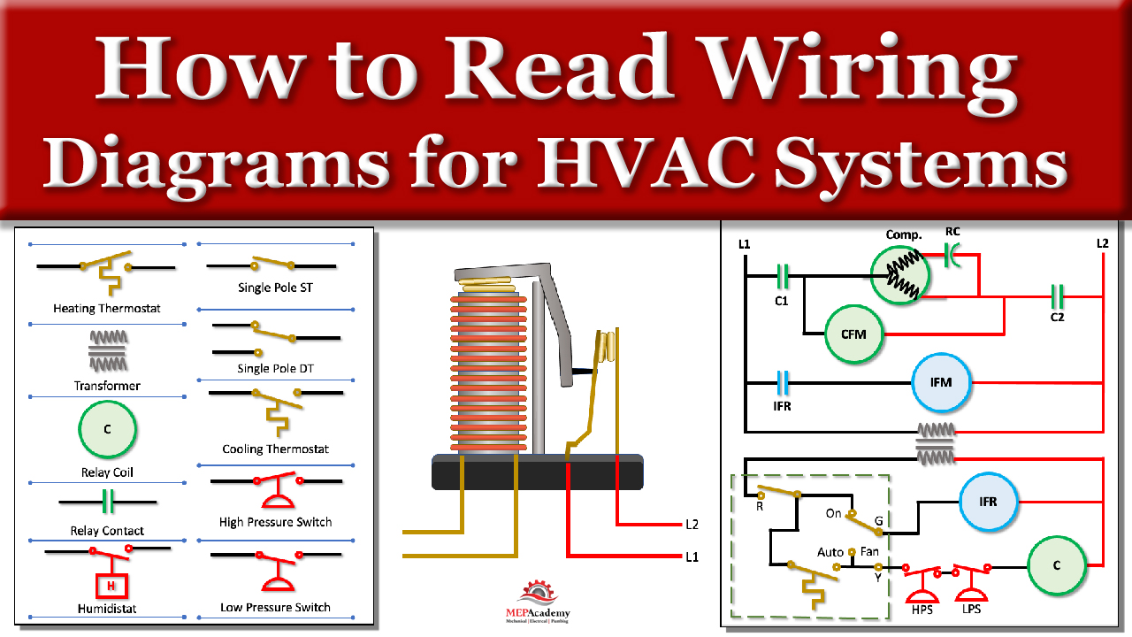
Schematics utilize a standardized language of symbols, lines, and alphanumeric codes to represent physical components and their electrical relationships. Solid lines typically indicate primary current-carrying wires, while dashed or dotted lines signify mechanical linkages, shielded cables, or components located within a separate module. Symbols represent resistors, diodes, capacitors, switches, and motors, usually accompanied by reference designations that map back to a parts list or harness layout.
Color coding on schematics helps technicians trace individual circuits across multiple pages of a service manual. It must be noted that wire insulation colors vary significantly between regions and applications, requiring close attention to the specific legend provided by the manufacturer. For foundational layout concepts, reviewing Wiring Diagram Basics clarifies how grid coordinates, connector pinout tables, and splice locations work together to form a complete map of the electrical architecture.
Common Problems and Troubleshooting Methods
Open circuits, short circuits to ground, and high-resistance faults represent the most frequent issues encountered during electrical diagnosis. An open circuit stops current flow entirely due to a broken wire or disconnected terminal. A short circuit occurs when a hot wire makes unintended contact with a grounded surface, instantly drawing maximum current and tripping the circuit protection. High-resistance faults develop from corrosion, loose crimps, or oxidized relay contacts, allowing some voltage to pass while starving the load of necessary operating current.
A systematic diagnostic approach uses the wiring schematic to isolate the fault without blindly replacing expensive components. Technicians begin by verifying the symptom, locating the relevant circuit on the diagram, and identifying all fuses, connectors, and splices in the path. Using a digital multimeter, voltage drop testing across loaded circuits reveals hidden resistance that visual inspections miss. When dealing with complex intermittent faults, exploring structured guides on Wiring Troubleshooting provides valuable frameworks for narrowing down elusive electrical gremlins.
Practical Tips and Safety Considerations
Working with electricity demands rigorous adherence to safety protocols to prevent personal injury and equipment damage. Mains-voltage installations and high-current automotive systems require de-energizing the circuit and verifying zero energy states with a calibrated meter before touching bare conductors. When handling vehicle systems, disconnecting the battery prevents accidental short circuits from tools bridging live terminals to the chassis. Qualified professionals must perform work in accordance with local regulations, such as the NEC or NFPA 70 in the United States, the CEC in Canada, BS 7671 in the UK, or AS/NZS 3000 in Australia.
One common mistake in the field involves probing delicate connector pins directly with oversized meter probes, which permanently widens female terminals and creates future intermittent connections. Always use back-probe pins or appropriate breakout adapters to test circuits safely. Selecting the correct wire gauge and insulation type for repairs prevents overheating and insulation breakdown over time. Proper heat shrinking and sealed crimp connectors protect spliced wires from moisture ingress, ensuring long-term reliability in harsh environments.
Conclusion
Wiring diagram decoding bridges the gap between mechanical complexity and logical electrical repair. By learning to interpret symbols, trace circuit paths, and apply systematic diagnostic methods, technicians and DIY enthusiasts can resolve faults efficiently and safely. Careful attention to manufacturer legends, regional standards, and proper testing techniques ensures successful installations and reliable electrical systems. Master these foundational reading skills to approach any complex electrical challenge with confidence.
Quick Wiring Specifications & Terminal Guide
| Component / Circuit | Standard Wire Gauge | Recommended Protection |
|---|---|---|
| Control & Trigger Signals | 18 – 20 AWG | 5A – 7.5A Inline Fuse |
| Standard Auxiliary Load | 14 – 16 AWG | 15A – 20A Circuit Breaker |
| Main Power Feed / Supply | 10 – 12 AWG | 30A – 40A Heavy-Duty Relay |
Images References