Introduction
Understanding how does a 4 pin 40 amp relay work is essential for anyone designing, maintaining, or troubleshooting high-current electrical circuits in automotive, marine, and industrial applications. A relay is an electrically operated switch that uses a low-power control circuit to open or close a high-power load circuit. Without these electromechanical components, dashboard switches and electronic control units would carry the full amperage of heavy accessories like headlights, cooling fans, and fuel pumps, resulting in massive switches, heavy wire harnesses, and severe voltage drops. Master technicians rely on a firm grasp of these devices to diagnose electrical faults efficiently, prevent catastrophic wiring failures, and ensure that auxiliary equipment draws power safely through dedicated circuits. By studying the internal mechanisms and terminal layouts found across various Relay and Component Wiring Diagrams, beginners and professionals alike can build safer, more reliable electrical systems.
💡 Technical Key Takeaways:
- Core Focus: Diagnostic schematic and terminal connection layout for How Does A 4 Pin 40 Amp Relay Work.
- Target Scope: Field technicians, automotive DIYers, and residential/commercial electricians.
- Safety Rule: Always disconnect the primary power source/battery terminal and verify zero voltage with a multimeter before touching wires.
Core Concepts and Wiring Fundamentals
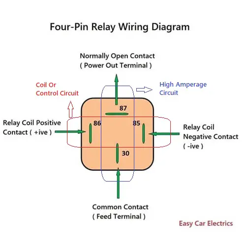
A standard automotive-style 4-pin 40-amp relay divides an electrical system into two distinct, isolated circuits: the control circuit and the load circuit. The control circuit utilizes thin-gauge wire to carry a fraction of an amp, energized by a low-current switch or ignition source. The load circuit utilizes thick-gauge wire—typically 10 AWG to 12 AWG depending on the draw and run length—to deliver heavy current directly from a protected power source, such as a battery or power distribution block, to the consumer device. Regional installation standards, such as SAE guidelines in North America or relevant international standards elsewhere, govern wire sizing and overcurrent protection requirements to prevent thermal overload.
Inside the molded plastic housing, the control circuit features a copper wire coil wrapped around an iron core. When voltage is applied across the coil terminals, current flowing through the windings generates a powerful electromagnetic field. This magnetic force pulls a spring-loaded steel armature downward, physically closing a set of heavy-duty silver-cadmium oxide contacts. These contacts bridge the gap between the power source and the load device. Once power is removed from the coil, the electromagnetic field collapses, and the internal tension spring instantly snaps the armature back to its resting position, cutting power to the accessory.
[Finding] — According to the National Fire Protection Association (NFPA) and standard automotive engineering analyses, loose high-current terminal connections are a primary contributor to localized high resistance and subsequent thermal degradation in mobile electrical systems.
Diagram Explanation and Key Components
Interpreting schematics for this device requires understanding standardized numbering conventions established by the Society of Automotive Engineers (SAE) and the Deutsches Institut für Normung (DIN). On a standard 4-pin single-pole single-throw (SPST) relay, each terminal is marked with a specific numeric designation molded into the plastic base. Terminal 85 represents the ground feed for the electromagnetic control coil, while Terminal 86 serves as the switched positive trigger input for that same coil. The polarity on standard non-diode-suppressed relays does not affect coil operation, though adhering to specific circuit designs ensures predictable behavior.
On the high-current side of the assembly, Terminal 30 acts as the common feed, typically wired directly to a fused battery positive source. Terminal 87 serves as the normally open output contact, delivering current to the load only when the relay is energized. When technicians examine these schematics alongside Vehicle Wiring Diagrams, tracing the path from the battery through the fuse, into Terminal 30, and out through Terminal 87 clarifies exactly how power flows under operating conditions. Recognizing these standard symbols and numbers eliminates guesswork during complex diagnostic procedures.
Common Problems and Troubleshooting Methods
Systematic fault-finding on a high-current relay circuit requires a digital multimeter configured to measure DC voltage and resistance. A typical failure point involves internal contact pitting, which occurs over years of inductive arcing when heavy loads disconnect. When contacts weld shut or burn away entirely, the load remains permanently powered or fails to activate despite a clicking sound from the coil. Technicians must differentiate between a faulty coil, which results in an open circuit and zero click, and failed internal contacts, which allow the coil to energize mechanically without passing continuity across the load pins.
The diagnostic procedure begins by verifying that voltage is present at Terminal 30 using a reliable ground reference. Next, the technician tests for control voltage at Terminal 86 and continuity to ground at Terminal 85 while the control switch is activated. If the coil energizes—indicated by an audible click—but voltage fails to pass from Terminal 30 to Terminal 87, the internal contacts have failed. Technicians must also inspect the physical connector plugs for signs of heat stress, melted plastic, or corrosion caused by high resistance, often referencing Wiring Troubleshooting guides for advanced voltage drop testing methodologies.
Practical Tips and Safety Considerations
Installing and servicing high-amperage switching components demands strict adherence to electrical safety and mechanical best practices. Working on 12V or 24V DC automotive and equipment circuits requires disconnecting the battery negative terminal before cutting, stripping, or terminating heavy-gauge power leads to prevent accidental short circuits and severe burns. Technicians should always pair a 40-amp relay with an appropriately rated inline fuse or circuit breaker positioned as close to the power source as physically possible. This protects the supply wire from short-to-ground faults that occur before the current reaches the relay.
Wire sizing must match the 40-amp capacity of the relay; undersized conductors will act as heating elements, creating severe fire hazards. Crimp connections must be executed using professional ratchet crimp tools rather than standard pliers to ensure mechanical strength and low electrical resistance. Applying dielectric grease to connector terminals helps prevent moisture intrusion and subsequent oxidation, particularly in marine or under-hood environments. When dealing with complex secondary loads, technicians frequently cross-reference Appliance and Device Wiring principles to ensure proper isolation between control and power networks.
Conclusion
Mastering the operation, wiring layout, and diagnostic testing of a standard high-current switching component empowers technicians to build and maintain robust electrical systems. By separating low-current control signals from high-amperage power delivery, these devices protect sensitive switches, reduce voltage drop, and ensure reliable operation across demanding automotive and industrial environments. Systematic troubleshooting methods, proper wire sizing, and strict adherence to safety protocols prevent common failures like contact pitting and thermal overload. Continued study of fundamental electrical principles remains the cornerstone of professional installation and accurate fault diagnosis.
Quick Wiring Specifications & Terminal Guide
| Component / Circuit | Standard Wire Gauge | Recommended Protection |
|---|---|---|
| Control & Trigger Signals | 18 – 20 AWG | 5A – 7.5A Inline Fuse |
| Standard Auxiliary Load | 14 – 16 AWG | 15A – 20A Circuit Breaker |
| Main Power Feed / Supply | 10 – 12 AWG | 30A – 40A Heavy-Duty Relay |
Images References