Introduction
A 3 position switch schematic symbol is the standardized graphic representation used on technical blueprints to denote a manual control device capable of routing electrical current through three distinct operational states. This graphical shorthand appears frequently across Appliance and Device Wiring layouts, industrial control panels, and mobile machinery schematics. Mastering this symbol ensures technicians can trace power distribution accurately without guessing how internal contacts interact. Correct interpretation prevents miswiring, reduces diagnostic time, and maintains system integrity whether working on low-voltage DC electronics or heavier control circuits.
💡 Technical Key Takeaways:
- Core Focus: Diagnostic schematic and terminal connection layout for 3 Position Switch Schematic Symbol.
- Target Scope: Field technicians, automotive DIYers, and residential/commercial electricians.
- Safety Rule: Always disconnect the primary power source/battery terminal and verify zero voltage with a multimeter before touching wires.
Core Concepts and Wiring Fundamentals
Multi-position switches operate by mechanically shifting internal conductive bridges to connect a common terminal to one or more output paths. In electrical systems, these devices manage circuits by interrupting or redirecting current flow from a power source to a load, protected upstream by fuses or circuit breakers. Understanding Wiring Diagram Basics clarifies how terminals are designated.
Depending on the specific function, these switches can be maintained—meaning they stay in the selected position until physically moved—or momentary, returning via a spring to a center-off or resting state. Common configurations include Single Pole, Double Throw (SPDT) center-off, or Double Pole, Double Throw (DPDT) arrangements. Each variation dictates how supply voltage from the battery, transformer, or mains supply routes through wires and connectors to downstream components.
[Standardization] — The International Electrotechnical Commission (IEC) and the National Electrical Manufacturers Association (NEMA) maintain standardized graphical symbols for switches to ensure universal recognition across international engineering disciplines.
Diagram Explanation and Key Components
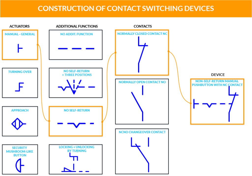
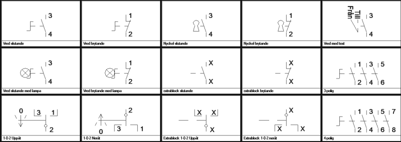
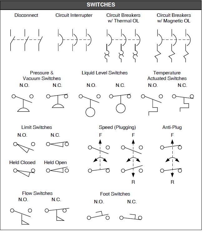
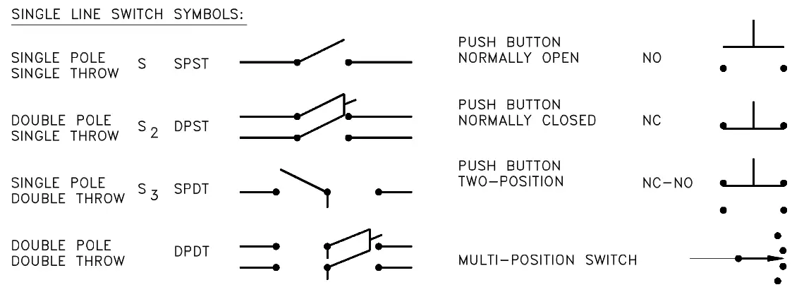
Reading a 3 position switch schematic symbol requires identifying the common terminal line, the movable actuator arm, and the individual contact points representing each physical setting. A typical symbol displays a dashed line linking ganged poles, static contact dots labeled with numbers or letters, and a pivoting lever line that points toward the active contact. Dashed lines indicate mechanical linkage between multiple poles within a single physical housing.
Color coding on accompanying wiring diagrams varies by region and application. In automotive and low-voltage DC installations governed by standards such as SAE J1128, wire insulation colors specify functions like power feed or ground, though aftermarket switches may use arbitrary lead colors. In UK and European mains applications adhering to BS 7671, color designations differ significantly from North American NEC or Canadian CEC practices, requiring careful reference to the manufacturer legend rather than relying solely on wire color.
Common Problems and Troubleshooting Methods
Systematic fault-finding on multi-position circuits involves isolating whether a malfunction stems from the switch itself, external wiring, or the connected load. Typical failure points include internal contact arcing, mechanical wear of the spring-return mechanism, and high-resistance corrosion on terminal spade connectors.
A structured diagnostic approach begins with a visual inspection of connectors and wire crimps for signs of thermal damage. Next, using a digital multimeter set to continuity or resistance mode while the system is de-energized, technicians verify that the switch closes the correct circuits in position one, opens everything in position two, and closes the alternate circuit in position three. Voltage drop testing under load reveals high-resistance contacts that pass a simple continuity test but fail when carrying operational current.
Practical Tips and Safety Considerations
Working with electrical control circuits demands strict adherence to safety protocols to prevent personal injury and equipment damage. Prior to conducting any physical inspection, modification, or continuity testing, always de-energize the circuit and verify zero energy state with a calibrated multimeter; for automotive work, disconnect the negative battery terminal, and for mains applications, isolate the supply breaker.
When replacing a component, match the switch amperage and voltage rating precisely to the load requirements to prevent overheating. Avoid common installation mistakes such as loose terminal screw torque or inadequate wire stripping length, which can lead to intermittent open circuits. Always consult local regulations, such as the NEC in the US or AS/NZS 3000 in Australia, and engage a licensed electrician or qualified technician where local law dictates.
Conclusion
Interpreting a 3 position switch schematic symbol is an essential skill for diagnosing and installing multi-state control systems across diverse technical fields. Careful analysis of terminal designations, combined with methodical multimeter testing, allows technicians to resolve faults efficiently. For further exploration of complex control architectures, reviewing Relay and Component Wiring Diagrams provides additional insight into system integration.
Quick Wiring Specifications & Terminal Guide
| Component / Circuit | Standard Wire Gauge | Recommended Protection |
|---|---|---|
| Control & Trigger Signals | 18 – 20 AWG | 5A – 7.5A Inline Fuse |
| Standard Auxiliary Load | 14 – 16 AWG | 15A – 20A Circuit Breaker |
| Main Power Feed / Supply | 10 – 12 AWG | 30A – 40A Heavy-Duty Relay |
Images References