Introduction
Reading wire symbols on wiring schematic drawings is a foundational skill for interpreting electrical blueprints across automotive, residential, and industrial applications. A schematic translates physical hardware into a standardized graphic language, utilizing universal symbols to represent conductors, control elements, and protective devices. Mastering this visual vocabulary allows technicians and DIY enthusiasts to trace circuits efficiently, verify system integrity, and perform accurate fault-finding without guessing. Proper interpretation improves safety by ensuring loads, wire gauges, and overcurrent protection match design requirements before power is ever applied. These blueprints appear in Wiring Diagram Basics guides, serving as maps for assembling, maintaining, and troubleshooting complex electrical architecture.
💡 Technical Key Takeaways:
- Core Focus: Diagnostic schematic and terminal connection layout for Wire Symbols On Wiring Schematic.
- Target Scope: Field technicians, automotive DIYers, and residential/commercial electricians.
- Safety Rule: Always disconnect the primary power source/battery terminal and verify zero voltage with a multimeter before touching wires.
Core Concepts and Wiring Fundamentals
An electrical schematic relies on a logical network of pathways and components designed to deliver electrical energy from a source to a load. Power sources, such as a 12-volt automotive battery or a household alternating current supply, inject energy into the circuit, while conductive lines direct that flow. Conductors are represented by solid lines, with specific line weights or line styles denoting single conductors, bundled harnesses, or shielded cables.
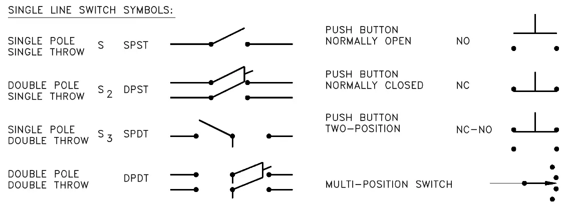
Control elements interrupt or redirect this flow under manual or automatic operation. Switches open or close a circuit manually, whereas electromechanical switches, such as relays governed by the Relay and Component Wiring Diagrams category, manage high-current paths using low-current control triggers. Protective devices like fuses and circuit breakers stand guard against overcurrent conditions, automatically interrupting the circuit if current draw exceeds safe thresholds.
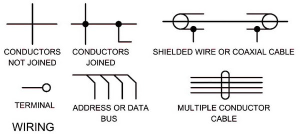
Ground points complete the circuit loop back to the power source or chassis, serving as the essential return path in direct current systems or the earth reference in alternating current installations. Connectors, splices, and terminal blocks dictate where physical wires join, and their graphic representations indicate whether wires cross without connecting or form a hard electrical junction denoted by a solid node dot.
Electrical faults involving improper component sizing and unrated connections remain a leading factor in electrical fires investigated by safety authorities. — National Fire Protection Association (NFPA)
Diagram Explanation and Key Components
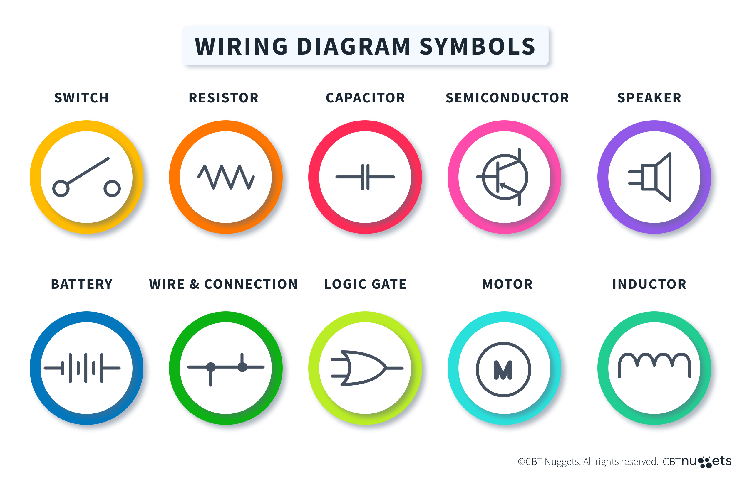
Understanding wire symbols on wiring schematic documents requires recognizing standard graphic shapes that correspond to physical hardware. A straight line represents a wire, but zig-zag lines or rectangular blocks designate resistors, parallel lines denote capacitors, and coiled loops indicate inductors or relay coils. Switches are drawn with an open or closed mechanical blade, while light bulbs, motors, and heating elements are enclosed within circles or specialized bounding shapes.
Color codes on schematics often provide critical context for physical identification, though regional differences must be considered. For example, residential wiring standards under the National Electrical Code (NEC) in the US and the Canadian Electrical Code (CEC) utilize specific conductor insulation colors for hot, neutral, and ground wires, which differ from the brown, blue, and green-yellow standard mandated by BS 7671 in the UK and AS/NZS 3000 in Australia. Automotive and low-voltage schematics frequently use alphanumeric codes next to wire symbols to designate both circuit function and wire insulation color.
Junctions require careful observation. When two lines cross on a diagram, a curved bridge or a simple gap indicates they are electrically isolated from one another. Conversely, a prominent black dot at the intersection confirms a permanent electrical splice. Terminal designations, pin numbers, and connector identifiers accompany these symbols to bridge the gap between abstract drawings and physical components found in Appliance and Device Wiring layouts.
Common Problems and Troubleshooting Methods
Systematic troubleshooting bridges the gap between schematic symbols and physical reality when diagnosing faults such as open circuits, short circuits, high-resistance grounds, and blown fuses. An open circuit stops current flow entirely, often caused by a broken wire, a loose connector pin, or an internal switch failure. A short circuit occurs when a hot conductor touches ground or a neutral prematurely, drawing excessive current and instantly tripping the system’s protective fuse.
Diagnostic procedures begin with a visual inspection of the circuit against the schematic, looking for burnt insulation, corrosion at ground studs, or loose terminal screws. Technicians then deploy a digital multimeter to measure voltage drops across components or test for continuity along specific diagrammed runs. For intermittent faults, isolating the circuit into smaller logical sections using the schematic allows for targeted probing, confirming whether power reaches both sides of a control switch, relay contact, or fuse block.
Practical Tips and Safety Considerations
Working safely with electrical systems requires strict adherence to energy control protocols and environmental standards. Before beginning any physical intervention on mains-voltage systems or high-current automotive circuits, technicians must de-energize the equipment, lock out and tag out the power source, and verify a zero-energy state using a reliable voltage tester or multimeter. In automotive environments, disconnecting the negative battery terminal prevents accidental short circuits and electronic module damage.
Compliance with local regulations is mandatory for all installations. Professional guidance from a licensed electrician or qualified technician must be sought where local law or building codes require certified labor. When replacing wires, fuses, or components, exact matches for ampacity, voltage rating, and temperature tolerance must be used. Undersized conductors or mismatched fuses invite thermal overload, insulation breakdown, and catastrophic failure.
Conclusion
Interpreting wire symbols on wiring schematic blueprints empowers technicians, mechanics, and DIY hobbyists to approach electrical work with confidence and precision. By understanding how schematic lines, control components, protective devices, and regional color codes translate to real-world hardware, diagnostics become logical rather than speculative. Prioritizing safety practices, verifying circuit de-energization, and consulting regional standards ensure that every installation or repair meets professional benchmarks of quality and reliability.
Quick Wiring Specifications & Terminal Guide
| Component / Circuit | Standard Wire Gauge | Recommended Protection |
|---|---|---|
| Control & Trigger Signals | 18 – 20 AWG | 5A – 7.5A Inline Fuse |
| Standard Auxiliary Load | 14 – 16 AWG | 15A – 20A Circuit Breaker |
| Main Power Feed / Supply | 10 – 12 AWG | 30A – 40A Heavy-Duty Relay |
Images References