Introduction
A buzzer schematic symbol represents an electromechanical or solid-state audio-signaling device utilized in electrical schematics to alert operators or users when specific circuit conditions are met. Interpreting this symbol correctly matters because failure to recognize audio alert indicators on complex blueprints can lead to misdiagnosed faults, bypassed safety interlocks, or improperly configured control panels. These symbols appear across multiple domains, from industrial automation logic loops to Appliance and Device Wiring found in modern residential kitchens. Understanding the graphical representation improves safety, streamlines troubleshooting accuracy, and ensures that installations comply with manufacturing standards.
💡 Technical Key Takeaways:
- Core Focus: Diagnostic schematic and terminal connection layout for Buzzer Schematic Symbol.
- Target Scope: Field technicians, automotive DIYers, and residential/commercial electricians.
- Safety Rule: Always disconnect the primary power source/battery terminal and verify zero voltage with a multimeter before touching wires.
Core Concepts and Wiring Fundamentals
Buzzers operate by converting electrical energy into audible sound waves through rapid mechanical interruption or electronic oscillation. Low-voltage direct current systems, typical in automotive configurations governed by standards from the Society of Automotive Engineers (SAE), commonly run buzzers on twelve or twenty-four volts supplied through switched control circuits, fuses, and dedicated ground paths. In contrast, residential applications or commercial control panels may integrate buzzers into alternating current control loops managed by step-down transformers.
Control circuits activate the buzzer via relays, switches, or solid-state transistors, isolating the low-power signaling device from heavy load currents. Fuses protect these auxiliary circuits from overcurrent conditions, preventing insulation degradation or wiring harness damage. Ground integrity remains vital for electromechanical buzzers, as high-resistance grounds cause intermittent chattering or total operational failure.
Electromechanical and solid-state acoustic indicators require specific consideration of inductive kickback protection, where flyback diodes are typically placed across DC buzzer coils to prevent voltage spikes from damaging sensitive electronic control modules. — National Fire Protection Association (NFPA) / IEEE Standard Practices
Diagram Explanation and Key Components
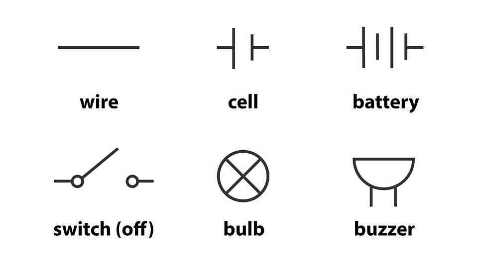
The standard buzzer schematic symbol generally resembles a half-circle or a stylized cross-section of a megaphone, oriented to emit sound waves toward the viewer or away from the core circuit line. Reviewing Wiring Diagram Basics helps technicians identify polarity markings, such as positive (+) and negative (-) terminals, which are critical for polarized electronic buzzers and piezoelectric sounders.
Letter designations on blueprints typically label a buzzer with the prefix “BZ” followed by a numerical identifier like BZ1 or BZ2. Interconnecting lines display the routing from the power source through control contacts to the buzzer terminal. Wire color codes vary significantly by region; for instance, North American automotive wiring often relies on standard color charts governed by SAE guidelines, whereas installations in the United Kingdom and Australia follow distinct regional color practices outlined by the British Standards Institution (BS 7671) and Standards Australia (AS/NZS 3000).
Common Problems and Troubleshooting Methods
Systematic fault-finding for a buzzing or silent circuit requires a logical diagnostic approach using a digital multimeter to isolate power, control, and ground issues. Typical failures include open-circuit buzzer coils, blown control fuses, corroded connector terminals, or failing solid-state driver transistors on control boards.
Technicians begin diagnosis by verifying voltage at the buzzer terminals when the activating condition is present. If proper operating voltage is measured across the terminals but no sound is emitted, the internal coil or piezoelectric element has failed open. If zero voltage is present, the technician traces backward through the circuit map, inspecting upstream fuses, relay contacts, and control switches. Ground continuity must also be verified using resistance measurements to ensure high-resistance paths are not dropping the applied supply voltage below operational thresholds.
Practical Tips and Safety Considerations
Adhering to strict safety protocols is mandatory when servicing circuits that incorporate audible signaling devices, especially when those circuits interface with mains voltage or high-current vehicle systems. Before performing any physical inspection or wiring modification, de-energize the circuit and verify zero energy state with a calibrated voltage tester. When working on mobile equipment, disconnect the battery negative terminal to eliminate short-circuit hazards.
Field experience shows that a frequent mistake involves replacing a blown fuse without identifying the underlying short circuit, which leads to immediate repeat failures. Technicians should always match replacement wire gauge and insulation ratings to the original equipment manufacturer specifications. For complex multi-tier control systems, consulting resources dedicated to Relay and Component Wiring Diagrams ensures proper integration of auxiliary warning devices without overloading control modules.
Conclusion
Mastering the interpretation of the buzzer schematic symbol empowers technicians and DIY enthusiasts to diagnose audio alert faults rapidly and maintain electrical systems effectively. Proper identification of component labels, terminal polarities, and associated control wiring prevents costly misdiagnoses during troubleshooting procedures. Safety diligence, adherence to regional electrical codes, and methodical circuit tracing remain foundational practices across automotive, appliance, and industrial installations. Further exploration of Wiring Troubleshooting methodologies provides additional depth for resolving complex electrical anomalies.
Quick Wiring Specifications & Terminal Guide
| Component / Circuit | Standard Wire Gauge | Recommended Protection |
|---|---|---|
| Control & Trigger Signals | 18 – 20 AWG | 5A – 7.5A Inline Fuse |
| Standard Auxiliary Load | 14 – 16 AWG | 15A – 20A Circuit Breaker |
| Main Power Feed / Supply | 10 – 12 AWG | 30A – 40A Heavy-Duty Relay |
Images References