Introduction
A ford one wire alternator diagram outlines a simplified 12V DC vehicle charging architecture that eliminates traditional external voltage regulator harnesses in favor of an internal self-exciting regulator. This modification is frequently applied during engine swaps, hot rod builds, and vintage restorations to clean up engine bay clutter. Understanding this schematic layout helps technicians and enthusiasts simplify vehicle electrical systems while maintaining reliable battery charging output. Proper interpretation of these schematics ensures safe installation, prevents catastrophic electrical fires, and improves overall diagnostic accuracy during charging system failures.
💡 Technical Key Takeaways:
- Core Focus: Diagnostic schematic and terminal connection layout for Ford One Wire Alternator Diagram.
- Target Scope: Field technicians, automotive DIYers, and residential/commercial electricians.
- Safety Rule: Always disconnect the primary power source/battery terminal and verify zero voltage with a multimeter before touching wires.
Core Concepts and Wiring Fundamentals
Vehicle charging systems rely on electromagnetic induction to convert mechanical engine rotation into usable electrical current. A standard Ford alternator typically requires a multi-pin stator, rotor, and external or internal regulator setup involving multiple control wires. Converting to a single-wire configuration condenses this complexity by utilizing an internal self-exciting voltage regulator. When engine speed reaches a specific threshold known as the cut-in RPM, internal circuitry senses rotor rotation and initiates the field current without requiring an ignition switch excitation signal. Power generation begins immediately, routing high-amperage direct current straight to the battery positive terminal.
High-current delivery requires heavy-gauge copper conductors to prevent voltage drop and excessive heat generation. The single output stud on the alternator connects directly to the vehicle starter solenoid battery post or the positive battery terminal via a properly sized fusible link or dedicated circuit breaker. Regional standards governed by organizations like the Society of Automotive Engineers (SAE) dictate minimum conductor cross-sectional areas based on expected alternator output capacity, typically ranging from 60 to over 100 amperes on modified street vehicles.
[Finding] — According to automotive electrical safety guidelines established by the Society of Automotive Engineers (SAE), unprotecting high-amp alternator output leads without a properly rated fusible link or circuit breaker is a primary cause of engine compartment electrical fires.
Diagram Explanation and Key Components
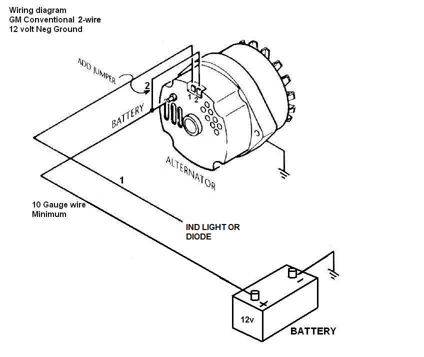
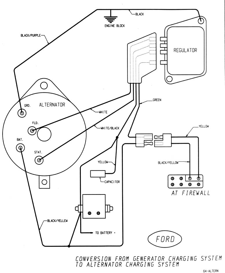
Reading a ford one wire alternator diagram requires recognizing simplified schematic symbols that represent the battery, charging indicator lamp options, the main output stud, and internal diode assemblies. Unlike factory wiring diagrams that display complicated multi-pin plastic connectors, dash warning lights, and ignition feed wires, the one-wire schematic isolates the primary power pathway. The main battery feed is represented by a heavy solid line connecting the alternator output terminal (often labeled BAT) directly to the main power distribution point.
Internal components inside the alternator housing include the rectifier bridge, which converts alternating current generated within the stator windings into direct current for the vehicle accessories and battery. The internal voltage regulator monitors system voltage and modulates field current to maintain a stable 13.5 to 14.5 volts while the engine runs. Wire color codes vary significantly between aftermarket conversion kits and original equipment manufacturer harnesses, making it essential to trace physical circuits rather than relying solely on factory color charts. Reviewing Vehicle Wiring Diagrams helps clarify how this modified circuit interfaces with standard chassis harnesses.
Common Problems and Troubleshooting Methods
Diagnosing charging issues on a single-wire setup involves a systematic diagnostic procedure using a digital multimeter set to DC volts and current clamps. Typical faults include low charging output, battery drain caused by internal regulator leakage, and intermittent charging failure until the engine is revved past the cut-in speed. Mechanics often encounter charging dropouts if the main output cable is undersized or if high-resistance corrosion develops at terminal connections.
Begin the diagnostic process by verifying battery state of charge and checking all mechanical belt tensions. Measure voltage directly across the battery terminals with the engine idling; a healthy system should display between 13.5V and 14.5V. If voltage remains at static battery levels (around 12.6V), test for voltage drop along the main charging cable by placing multimeter leads between the alternator output stud and the positive battery post during operation. For further insights into systematic fault-finding across other automotive systems, consult resources on Wiring Troubleshooting to refine diagnostic technique.
Practical Tips and Safety Considerations
Working with high-amperage charging circuits demands strict adherence to safety protocols, including disconnecting the negative battery cable before servicing any alternator connections. Because the main output stud maintains a direct, unfused connection to the battery in many poorly executed conversions, accidental contact with grounded chassis components can cause severe arcing, tool welding, and battery explosion. Always incorporate an appropriately rated fusible link or mega-fuse matching the maximum output rating of the alternator.
Ensure proper chassis grounding between the engine block, chassis, and battery negative post, as inadequate grounding introduces severe resistance and forces the alternator to work harder. When routing heavy-gauge power cables away from hot exhaust manifolds and sharp sheet metal edges, utilize split-loom tubing, rubber grommets, and secure Adel clamps to prevent chafing and eventual short circuits. Technicians should also reference Relay and Component Wiring Diagrams when integrating auxiliary accessories that draw power from the upgraded charging system.
Conclusion
Implementing a simplified charging architecture requires careful attention to conductor sizing, mechanical security, and foundational electrical principles. While these systems reduce under-hood wiring complexity, they still demand precise installation practices to guarantee long-term reliability and vehicle safety. By mastering the interpretation of these schematics and executing disciplined diagnostic steps, technicians and DIY builders can ensure optimal vehicle electrical performance. Explore Wiring Diagram Basics to continue building comprehensive electrical competency across all automotive systems.
Quick Wiring Specifications & Terminal Guide
| Component / Circuit | Standard Wire Gauge | Recommended Protection |
|---|---|---|
| Control & Trigger Signals | 18 – 20 AWG | 5A – 7.5A Inline Fuse |
| Standard Auxiliary Load | 14 – 16 AWG | 15A – 20A Circuit Breaker |
| Main Power Feed / Supply | 10 – 12 AWG | 30A – 40A Heavy-Duty Relay |
Images References