Introduction
Dump trailer solenoid wiring encompasses the electrical circuits that control heavy-duty hydraulic lift systems on commercial and utility trailers. This setup bridges low-current dashboard controls and high-amperage battery power to operate the hydraulic pump motor. Understanding this configuration ensures reliable dumping cycles, prevents premature component failure, and protects the towing vehicle’s electrical infrastructure. Improper connections often lead to voltage drop, burnt relay contacts, or stalled hydraulic rams during critical lifts. Mastering these diagrams and procedures directly improves diagnostic speed and operational safety in the field. Further insights into mobile electrical systems are available within Vehicle Wiring Diagrams for broader context on auxiliary power distribution.
💡 Technical Key Takeaways:
- Core Focus: Diagnostic schematic and terminal connection layout for Dumptrailer Solenoid Wiring.
- Target Scope: Field technicians, automotive DIYers, and residential/commercial electricians.
- Safety Rule: Always disconnect the primary power source/battery terminal and verify zero voltage with a multimeter before touching wires.
Core Concepts and Wiring Fundamentals
Dump trailer solenoid wiring relies on a continuous duty or intermittent high-current relay, commonly referred to as a starter solenoid or motor reversing contactor. The system draws direct current from a 12V or 24V deep-cycle battery mounted on the trailer frame. A low-amperage control circuit runs from the wired handheld pendant or cab-mounted rocker switch to the small activation terminal on the solenoid.
When the switch closes, it energizes an internal electromagnetic coil within the solenoid. This action pulls a heavy copper disc against two large contact studs, bridging the battery positive cable to the hydraulic pump motor. Because these pump motors draw massive amounts of current—often exceeding 150 to 300 amperes under load—the solenoid acts as a remote switch that keeps heavy cables safely outside the operator cab.
Chassis grounding is a critical element in these mobile installations. Many technicians make the mistake of relying solely on the trailer hitch ball for ground return. A dedicated, heavy-gauge negative cable must run directly from the battery negative post to the hydraulic pump mounting bracket and trailer frame. High resistance in this return path generates excessive heat and reduces motor speed.
[High-Current DC Risks] — According to guidelines from the Society of Automotive Engineers (SAE), DC circuits carrying over 100 amperes require properly rated overcurrent protection, such as manual-reset circuit breakers, positioned within inches of the power source to prevent catastrophic harness fires during a short circuit.
Diagram Explanation and Key Components
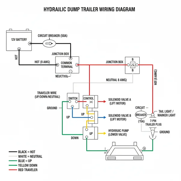
Reading a schematic for dump trailer solenoid wiring requires recognizing standard automotive and industrial electrical symbols. The battery is typically represented by alternating long and short parallel lines. Fuses and circuit breakers appear as jagged lines or rectangular boxes with rating values. Solenoids are depicted with an outer coil symbol and heavy switch contacts bridging the primary power path.
Color coding varies significantly by region and manufacturer. In North America (following conventions influenced by SAE), red wires generally denote unswitched battery positive, while yellow or orange wires carry switched control signals. In the UK, Europe, and Australia (following BS 7671 or local automotive practices), brown or red often serves as the primary power conductor, with various secondary colors utilized for control lines. Always verify wire functions with a multimeter rather than relying solely on jacket colors.
The main components include the power source, fuse or circuit breaker, remote control pendant, solenoid relay, hydraulic pump motor, and physical chassis grounds. Each part plays a specific role in managing electrical flow and mechanical actuation. For a deeper look into how these switches operate within larger control loops, consult Relay and Component Wiring Diagrams for detailed pin configurations.
Common Problems and Troubleshooting Methods
Systematic fault-finding in dump trailer solenoid wiring isolates issues between the control side and the high-current power side. A common failure mode involves a clicking sound from the solenoid without motor movement. This audible click indicates that the low-current control circuit and internal coil are functioning, but the heavy internal contacts are pitted, welded open, or failing to pass voltage to the pump motor.
When the solenoid remains completely silent upon switch activation, begin diagnosis at the control pendant. Use a digital multimeter set to DC volts to verify voltage at the switch input. Next, press the raise button and check for voltage at the small control terminal of the solenoid. The absence of voltage here points toward a blown inline fuse, a severed wire in the remote tether, or a faulty toggle switch.
If control voltage is present at the small terminal but the solenoid does not click, measure the voltage drop across the main power studs while under load. A severe drop indicates either a discharged battery, loose terminal connections, or burnt contacts inside the relay. Technicians should approach these diagnostics methodically, avoiding random component replacement. Structured testing procedures of this nature are further outlined in Wiring Troubleshooting guides.
Practical Tips and Safety Considerations
High-current DC circuits demand strict adherence to safety protocols and installation best practices. Before performing any physical work or replacing components, always disconnect the trailer battery to eliminate the risk of accidental arcing or severe electrical shock. Mechanics must remove metal jewelry, wear eye protection, and use insulated hand tools when working near unswitched battery terminals.
Wire sizing is paramount when dealing with hydraulic pump motors. Using undersized conductors creates excessive resistance, starving the motor of necessary amperage and causing thermal degradation of the wire insulation. Match the cable gauge strictly to the pump manufacturer specifications, typically utilizing heavy 2-AWG or 4-AWG copper cables for the primary motor circuit.
Protect all exposed terminals with dielectric grease and heavy-wall heat shrink tubing to prevent moisture ingress and road salt corrosion. Trailer wiring endures constant vibration, moisture, and physical stress. Securing harnesses with rubber-lined clamps every few inches prevents chafing against sharp steel frame rails, ensuring long-term reliability of the entire dump bed system.
Conclusion
Mastering dump trailer solenoid wiring requires an appreciation for both low-current control logic and high-amperage power distribution. Proper component selection, secure grounding, and systematic diagnostic workflows prevent costly downtime and operational hazards. By adhering to established regional standards and maintaining clean, protected connections, technicians ensure safe and repeatable lifting performance. Explore additional reference materials within Wiring Diagram Basics to strengthen fundamental schematics comprehension across all mobile and stationary applications.
Quick Wiring Specifications & Terminal Guide
| Component / Circuit | Standard Wire Gauge | Recommended Protection |
|---|---|---|
| Control & Trigger Signals | 18 – 20 AWG | 5A – 7.5A Inline Fuse |
| Standard Auxiliary Load | 14 – 16 AWG | 15A – 20A Circuit Breaker |
| Main Power Feed / Supply | 10 – 12 AWG | 30A – 40A Heavy-Duty Relay |
Images References