Introduction
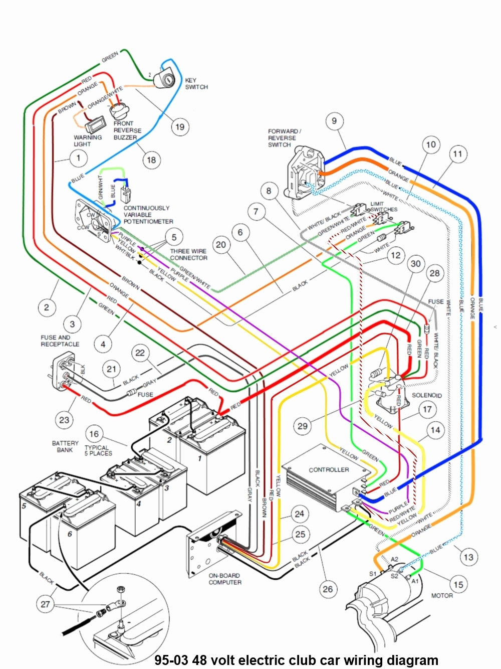
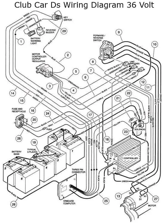
Club car wiring 48 v for hradlights governs the integration of aftermarket or factory illumination into high-voltage electric utility vehicles. This electrical task matters because golf carts operate on direct current (DC) traction battery banks that exceed standard automotive thresholds. Applying improper voltage directly to standard 12-volt bulbs causes catastrophic thermal failure and fire hazards. Technicians encounter these circuits in golf courses, gated communities, and industrial facilities across North America, the UK, and Australia. Understanding this architecture improves safety, prevents component burnout, and ensures reliable night operation. For broader context on automotive circuits, consult Vehicle Wiring Diagrams.
💡 Technical Key Takeaways:
- Core Focus: Diagnostic schematic and terminal connection layout for Club Car Wiring 48 V For Hradlights.
- Target Scope: Field technicians, automotive DIYers, and residential/commercial electricians.
- Safety Rule: Always disconnect the primary power source/battery terminal and verify zero voltage with a multimeter before touching wires.
Core Concepts and Wiring Fundamentals
Electric utility vehicles derive movement from a series-connected battery pack totaling 48 volts DC. Headlights require a lower operating potential, typically 12 volts, to function correctly without premature filament failure. Direct connection of a 12-volt load across the entire 48-volt source results in an overvoltage condition that destroys the equipment instantly. Voltage reduction occurs through dedicated power conversion devices rather than tapping into individual batteries within the pack.
Tapping individual 12-volt batteries within a 48-volt series string creates an asymmetric state of charge across the pack. This imbalance forces the charging system to overwork specific batteries while undercharging others, leading to premature battery degradation. Proper installation utilizes a DC-to-DC converter to step down the full 48-volt supply to a stable 12-volt output. This device distributes the electrical load evenly across the entire battery bank.
Circuit protection remains mandatory on both the high-voltage input side and the low-voltage output side of the conversion unit. Fuses act as sacrificial weak links designed to melt and interrupt current flow during an accidental short circuit. Relay integration prevents heavy current draw from passing directly through dashboard toggle switches, extending component lifespans significantly. Detailed operational principles of switching devices are outlined in Relay and Component Wiring Diagrams.
[Electrical Safety Foundation International (ESFI)] — Improperly modified low-voltage circuits and overloaded battery taps are leading preventable causes of electrical fires in electric utility vehicles.
Diagram Explanation and Key Components
Schematics for club car wiring 48 v for hradlights rely on standardized symbols to denote power sources, conversion units, switches, and loads. Solid lines represent positive conductors, while dashed lines or designated symbols indicate chassis or return paths. Regional wiring color codes vary significantly; North American setups often use red for positive and black for negative, whereas British and Australian modifications may align with international standards utilizing brown and blue designations.
The main components consist of the 48-volt battery pack, an inline master fuse, a step-down voltage reducer, a dash-mounted control switch, and the lamp assemblies. The reducer features input terminals connected to the main battery positive and negative lines, alongside output terminals supplying regulated 12-volt power. The control switch interrupts either the low-current trigger wire of a relay or the main 12-volt feed running directly to the lamp filaments. Mastery of these visual notations begins with fundamental resources found in Wiring Diagram Basics.
Common Problems and Troubleshooting Methods
Systematic fault-finding processes isolate intermittent operational failures without damaging sensitive electronic modules. Typical field failures include blown fuses, oxidized ring terminals, loose battery post connections, and internal voltage reducer faults. Technicians must avoid guesswork and rely on structured diagnostic workflows.
Begin the diagnostic sequence by verifying battery pack voltage at the main terminals using a digital multimeter set to DC voltage. Proceed by testing the input side of the DC-to-DC converter to ensure 48 volts is reaching the unit. Check the output side to confirm a stable 12-volt reading when the key switch is active. Inspect the physical condition of all inline fuse holders for signs of thermal melting or corrosion. Test continuity across the dashboard switch terminals to verify proper internal contact closure when actuated. Finally, inspect the lamp grounds for secure metal-to-metal contact with the frame or dedicated negative bus bars. Further diagnostic strategies for complex electrical faults appear in Wiring Troubleshooting.
Practical Tips and Safety Considerations
Working with high-current DC systems demands strict adherence to safety protocols to prevent severe arc flashes and electrical shock. Always place the vehicle in the tow or maintenance mode switch before performing any physical wiring modifications. Disconnect the main battery negative cable to eliminate accidental short circuits while tightening terminals with insulated hand tools.
Select marine-grade copper wire sized appropriately for the expected current draw to prevent excessive voltage drop over long cable runs. Secure all wire harnesses away from sharp frame edges, moving steering linkages, and high-heat motor components using UV-resistant zip ties. Apply dielectric grease to all plug-in connectors and spade terminals to inhibit moisture intrusion and galvanic corrosion in outdoor environments. Adhere strictly to manufacturer specifications and regional codes such as the National Electrical Code (NEC) or BS 7671 where applicable.
Conclusion
Mastering club car wiring 48 v for hradlights ensures safe, reliable auxiliary lighting installation without compromising the primary traction battery architecture. Utilizing a dedicated DC-to-DC converter prevents destructive battery imbalances and protects sensitive 12-volt components from overvoltage stress. Systematic troubleshooting with a digital multimeter isolates faults quickly while minimizing downtime. Proper wire sizing, fusing, and secure grounding guarantee long-term operational integrity across diverse utility vehicle applications.
Quick Wiring Specifications & Terminal Guide
| Component / Circuit | Standard Wire Gauge | Recommended Protection |
|---|---|---|
| Control & Trigger Signals | 18 – 20 AWG | 5A – 7.5A Inline Fuse |
| Standard Auxiliary Load | 14 – 16 AWG | 15A – 20A Circuit Breaker |
| Main Power Feed / Supply | 10 – 12 AWG | 30A – 40A Heavy-Duty Relay |
Images References