Introduction
A briggs and stratton charging diagram serves as the definitive schematic blueprint for troubleshooting and repairing small engine electrical loops on lawn tractors, generators, and outdoor power equipment. Understanding this technical drawing matters because faulty charging systems lead to dead batteries, burnt stators, and unreliable engine starts. This schematic is used primarily in agricultural equipment, residential mowers, and portable utility generators across the United States, United Kingdom, Canada, and Australia. Proper comprehension improves safety, reduces diagnostic time, and ensures accurate electrical restoration when working on internal combustion auxiliary circuits found in Vehicle Wiring Diagrams.
💡 Technical Key Takeaways:
- Core Focus: Diagnostic schematic and terminal connection layout for Briggs And Stratton Charging Diagram.
- Target Scope: Field technicians, automotive DIYers, and residential/commercial electricians.
- Safety Rule: Always disconnect the primary power source/battery terminal and verify zero voltage with a multimeter before touching wires.
Core Concepts and Wiring Fundamentals
Small engine charging systems typically rely on permanent magnets mounted beneath the flywheel that rotate past stationary coils, known as stators, generating Alternating Current (AC) electricity. Alternating current refers to an electrical flow that periodically reverses direction, which must be converted into Direct Current (DC)—electricity flowing in a single, constant direction—to replenish a 12-volt lead-acid battery. On simpler engines, an alternating current output passes through a single diode to allow only half of the electrical wave to pass, creating a rudimentary half-wave rectified DC output suitable for trickle charging.
More robust engines utilize a dual-circuit stator or an external solid-state regulator-rectifier. A regulator-rectifier contains semiconductor diodes that convert alternating current into direct current while incorporating a voltage-limiting circuit to prevent overcharging the battery. The resulting direct current travels through insulated copper conductors, passes through an inline fuse protecting the main harness, and terminates at the positive battery terminal. Proper circuit continuity depends entirely on clean, corrosion-free connections at the terminal blocks and a solid metallic chassis ground to complete the return path.
[Fault Frequency] — According to small engine service data compiled by the Consumer Product Safety Commission (CPSC), corrosion and vibration-induced chafing in low-voltage wiring harnesses account for a significant majority of intermittent charging failures on outdoor power equipment.
Diagram Explanation and Key Components
Reading a briggs and stratton charging diagram requires familiarity with standardized symbols representing stators, diodes, fuses, switches, and battery loads. The schematic typically displays wire color codes using standard abbreviations, though exact hues can vary between manufacturing runs and regional specifications. For instance, alternating current leads originating under the flywheel often utilize black, yellow, or white wires, whereas regulated direct current output lines frequently employ red or orange insulation. Technicians must consult the specific engine identification number and manufacturer documentation to verify exact wire gauges and regional color deviations.
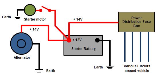
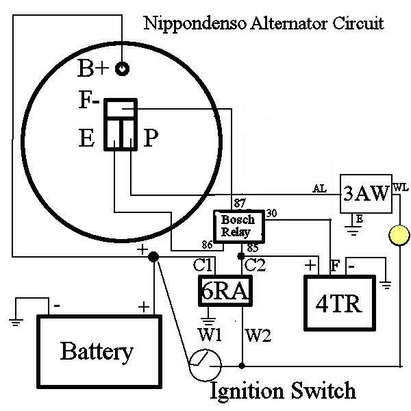
Key components include the alternator stator assembly, which provides the raw electrical output; the diode, which restricts current flow to a single direction; the regulator-rectifier module, tasked with voltage control; and the ignition switch, which ties the charging circuit into the broader machinery controls. Line types on the schematic differentiate between heavy-gauge high-current battery leads and thinner control circuit wires. Tracing these lines allows a technician to isolate whether a fault originates in the generating source, the conversion device, or the transmission wiring.
Common Problems and Troubleshooting Methods
Systematic fault-finding begins with verifying battery state of charge and inspecting all visible terminals for oxidation, looseness, or physical damage. Typical failures include open-circuited stator windings, shorted regulator-rectifiers, blown protective fuses, and high-resistance grounds caused by rust at the engine mounting points. To diagnose a non-charging condition safely, disconnect the negative battery cable before performing continuity or resistance checks on the harness.
Diagnostic testing proceeds through a structured sequence using a digital multimeter set to appropriate alternating and direct current voltage ranges. First, measure the raw AC voltage output directly from the stator leads while the engine runs at high idle; a reading below the manufacturer’s specified threshold indicates a failed stator or demagnetized flywheel. Next, check the direct current output downstream of the regulator-rectifier. If alternating current enters the regulator but no regulated direct current emerges, the regulator module has failed internally. For deeper insights into isolation techniques, review principles outlined in Wiring Troubleshooting.
Practical Tips and Safety Considerations
Executing electrical repairs on small engines demands strict adherence to workshop safety protocols and electrical standards established by organizations such as SAE International. Always disconnect the spark plug wire and negative battery terminal before cutting, splicing, or replacing harness sections to prevent accidental engine cranking or electrical sparks near fuel vapors. When replacing damaged conductors, match the original wire gauge and utilize high-temperature, oil-resistant automotive-grade insulation suitable for under-hood environments.
A frequent mistake during harness repair is twisting wires together and wrapping them in standard household electrical tape, which degrades rapidly under heat and oil exposure. Instead, employ crimp-sealed terminal connectors or solder joints protected with adhesive-lined heat shrink tubing to seal out moisture. Ensure all replacement fuses match the exact amperage rating specified by the manufacturer; installing an oversized fuse creates a severe fire hazard by allowing excessive current to melt the wiring harness before the protection device trips.
Conclusion
Mastering a briggs and stratton charging diagram empowers technicians and do-it-yourself enthusiasts to diagnose complex electrical faults accurately and restore dependable starting performance. By understanding stator generation, rectification, and harness routing, operators can prevent unexpected equipment downtime through methodical testing. Maintaining clean connections, using correct wire gauges, and adhering to safety standards ensure long-term reliability across all supported outdoor power applications. For further exploration of schematic symbols and layout principles, consult Wiring Diagram Basics.
Quick Wiring Specifications & Terminal Guide
| Component / Circuit | Standard Wire Gauge | Recommended Protection |
|---|---|---|
| Control & Trigger Signals | 18 – 20 AWG | 5A – 7.5A Inline Fuse |
| Standard Auxiliary Load | 14 – 16 AWG | 15A – 20A Circuit Breaker |
| Main Power Feed / Supply | 10 – 12 AWG | 30A – 40A Heavy-Duty Relay |
Images References