Introduction
A brake light switch diagram is a specialized schematic used to trace the electrical pathway responsible for illuminating the rear stop lamps whenever the brake pedal is depressed. Understanding this diagram is critical for automotive technicians, mobile mechanics, and DIY enthusiasts who need to diagnose intermittent rear illumination issues, cruise control disengagement failures, or shift-lock mechanism faults. This component bridges the gap between mechanical driver inputs and 12-volt vehicle circuitry, making it a foundational element found throughout comprehensive Vehicle Wiring Diagrams manuals. Mastering the layout prevents misdiagnoses, reduces labor times, and ensures legal road compliance across international jurisdictions.
💡 Technical Key Takeaways:
- Core Focus: Diagnostic schematic and terminal connection layout for Brake Light Switch Diagram.
- Target Scope: Field technicians, automotive DIYers, and residential/commercial electricians.
- Safety Rule: Always disconnect the primary power source/battery terminal and verify zero voltage with a multimeter before touching wires.
Core Concepts and Wiring Fundamentals
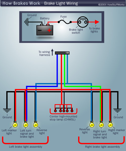
Modern automotive brake light circuits operate on a direct current 12V or 24V architecture, depending on whether the vehicle is a passenger car or a heavy-duty commercial truck. Power typically originates at the battery, passes through an engine compartment or cabin fuse box protected by a specific amperage fuse, and routes directly to the brake pedal switch mounted near the pedal bracket. When the driver presses the brake pedal, the internal contacts of the switch close, allowing current to flow toward the rear lamp assemblies. Older systems route this current directly through the switch contacts to the bulbs, while modern computer-managed architectures send a signal voltage input to the body control module or powertrain control module.
Ground distribution is equally vital within this subsystem, as a high-resistance ground path will cause dim bulbs, back-feeding, or erratic LED flashing behavior. Fuses protect against catastrophic short circuits, sacrificing themselves if a pinched wire touches chassis sheet metal. When evaluating these pathways, technicians often cross-reference standard Relay and Component Wiring Diagrams to determine if an auxiliary relay isolates heavy current draws from sensitive switch contacts.
[Society of Automotive Engineers (SAE) J1128] — Establishes stringent performance, insulation, and dimensional specifications for low-tension primary automotive wiring used in vehicle lighting and control circuits.
Diagram Explanation and Key Components
A brake light switch diagram uses standardized electrical symbols to represent the mechanical switch, constant power feeds, output lines, and destination loads. The switch itself is typically drawn either as a normally open push-button or a sliding plunger mechanism with multiple internal circuits. For instance, many modern vehicles utilize a dual-circuit switch where one set of contacts closes the brake lamps while the second set signals the engine computer to disengage cruise control or release the automatic transmission gear shifter. Wire colors on schematics follow manufacturer-specific standards governed by organizations like the Society of Automotive Engineers in North America or equivalent standards bodies in the UK, Europe, and Australia, meaning a green wire with a white tracer might denote a hot output line in one model while serving a different purpose elsewhere.
Connector pinouts on the diagram show exact cavity numbers, helping technicians probe the correct terminal using a digital multimeter without piercing wire insulation. Reading these schematics requires identifying line types: solid lines represent active power-carrying conductors, dashed lines often denote mechanical linkage or internal module functions, and cross-hatching indicates shielded harnesses. For broader system context, studying Wiring Diagram Basics helps beginners decode line weights, abbreviations, and connector locator charts effectively.
Common Problems and Troubleshooting Methods
Systematic fault-finding on brake light circuits begins by verifying battery state-of-charge and checking the integrity of the primary fuse supplying the pedal switch. A frequent field observation involves physical switch misalignment, where the plastic mounting tab wears down or shifts, preventing the plunger from extending fully when the pedal is released. Technicians also encounter oxidized connector pins caused by moisture ingress near the driver footwell or trunk compartments, leading to high-resistance open circuits. Diagnosing these faults requires a structured approach: first, check for battery voltage at the switch feed wire with the ignition on or off depending on the manufacturer design; second, depress the pedal and check for voltage on the output wire; third, inspect the bulb sockets and ground points at the rear corners of the vehicle. When symptoms point beyond simple component swaps, referencing advanced Wiring Troubleshooting guides provides methodical strategies for tracking down voltage drops and intermittent ground faults.
Practical Tips and Safety Considerations
Working on vehicle electrical networks demands strict adherence to safety protocols to prevent accidental airbag deployment, module damage, or electrical burns. Always disconnect the negative battery terminal before probing sensitive computer-controlled circuits with piercing tools or replacing hardwired harnesses. When repairing damaged sections of wire, avoid twisting conductors together; instead, use proper crimp connectors equipped with heat-shrink tubing or adhesive-lined butt splices to seal out moisture and road salt. Wire gauges must match factory specifications—typically ranging from 14 AWG to 18 AWG in automotive lighting applications—to prevent excessive resistance and thermal overload. Avoid bypassing fuses or installing higher-amperage fuses than specified by the manufacturer, as this creates a severe fire hazard. Technicians in the UK must ensure modifications comply with BS requirements where applicable, while North American mechanics should follow standards outlined by NFPA guidelines for vehicle safety.
Conclusion
Interpreting a brake light switch diagram transforms complex automotive electrical problems into logical, manageable diagnostic steps. By understanding power distribution, switch mechanics, and proper testing procedures, technicians and enthusiasts can resolve lighting failures safely and efficiently. Always consult up-to-date factory service manuals for exact pinouts, voltage parameters, and color codes specific to the vehicle make, model, and year. Review comprehensive Vehicle Wiring Diagrams to master your diagnostic skills and ensure reliable electrical repairs.
Quick Wiring Specifications & Terminal Guide
| Component / Circuit | Standard Wire Gauge | Recommended Protection |
|---|---|---|
| Control & Trigger Signals | 18 – 20 AWG | 5A – 7.5A Inline Fuse |
| Standard Auxiliary Load | 14 – 16 AWG | 15A – 20A Circuit Breaker |
| Main Power Feed / Supply | 10 – 12 AWG | 30A – 40A Heavy-Duty Relay |
Images References